 Copyright © Michael Richmond.
This work is licensed under a Creative Commons License.
Copyright © Michael Richmond.
This work is licensed under a Creative Commons License.
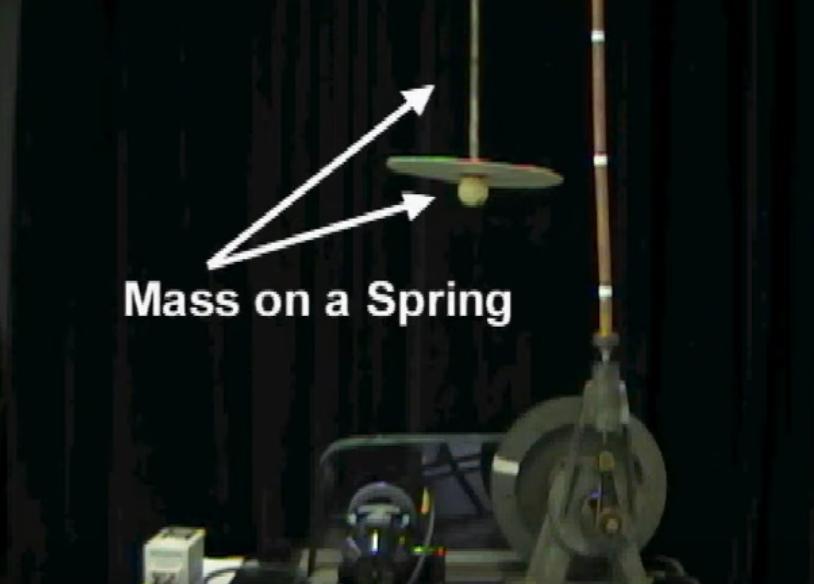
Click on the image to see a short video demonstrating forced harmonic motion.
Another nice video demonstrating the effects of forced HM is provided by Animated Science.
  Q:  Can you think of examples of forced harmonic motion in the
         real world?  Take one minute to ponder, and feel free to
         collaborate with other students.  Write down each example;
         we'll discuss them as a group.
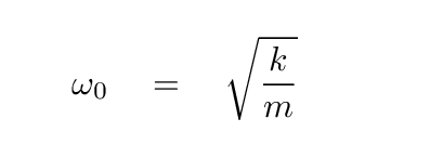
Let's begin with a situation we have discussed recently: a damped harmonic oscillator. For example, imagine a mass m hanging from a spring of force constant k. The undamped frequency of oscillations will be
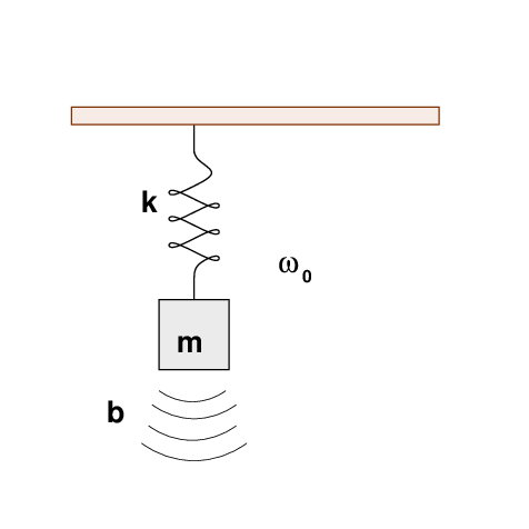
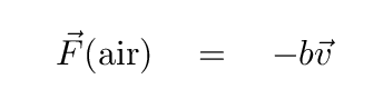
But since the mass and spring are in a room on Earth, they are immersed in air. A small force of air resistance, with coefficient b, acts to slow the mass down.
As we saw last time, the frequency of oscillation of this damped system will be slightly smaller than the frequency of the ideal, undamped system. Over time, the motions of the mass will slowly die away, until it comes to rest, motionless.
Fine.
But now, let's add one more component to the system. On top of the ceiling from which the spring is suspended, we place a metal bar which tilts up and down, up and down, driven by a motor at a constant frequency ω. This device exerts a periodic force with maximum amplitude Fmax on the spring.

What will happen to the mass and spring now? They are being driven at one frequency ω, but their natural response to displacement has a (probably) different frequency ω0. Which frequency will win? And how far will the mass bob up and down?
As usual, I will drop the vector signs at this point, simply for convenience.
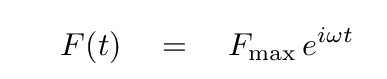
Let's represent the force on the spring+mass using exponential notation; we could use a plain old sine or cosine function, and end up with the same result, but the exponential form will make the following calculations more compact.
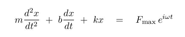
The differential equation of motion for the mass hanging from the spring now takes on a form we haven't seen before: one with a non-zero term on the right-hand side. This new term has units of force, just like all the other terms.
Let's also simplify the problem by ignoring the complex behavior of the mass immediately after we turn on the tilting device. Instead, we'll wait a minute, or an hour, until the system reaches a steady state, one that can be represented simply by some periodic function.
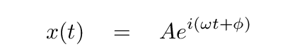
Finally, given all those conditions, we can GUESS that the motion of the mass might described by a familiar equation. The frequency ω here is exactly the same as that of the driving force; as long as we wait for the steady state, the system will end up at the driving frequency.
As usual, the real work will involve verifying that this guess really does satisfy the differential equation.
We'll also need to figure out the amplitude A of the motion, and its phase φ relative to the driving motor's motion.
Time to find out if our guess
will work. We'll need to write down the first and second derivatives with respect to time.
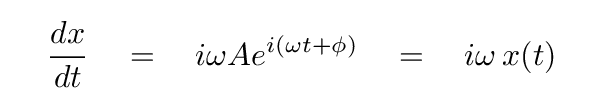
Q: What is the first derivative dx/dt?
Q: What is the second derivative d2x/dt2?

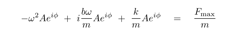
Okay. We can now insert these expressions into the differential equation, and hope that it causes the left-hand side to equal the right-hand side.
  Q:  Re-write this equation, inserting the expressions above
           for the derivatives of x(t).

It's hard to tell if the two sides are equal. Let's do a bit of of algebra to simplify.
First, we can divide both sides by eiωt.

Next, we can divide by the mass m.
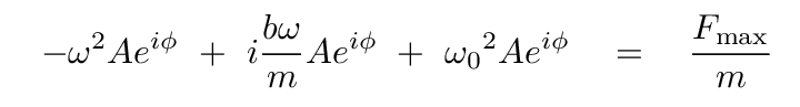
  Q:  The coefficient of the third term on the left-hand side
            includes a factor of k/m.   Is there any
            way to write that as a frequency?
Indeed there is. As you will see in just a moment, this will be very useful, because it will allow us to compare naturally the coefficients of the first and third terms.
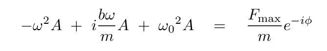
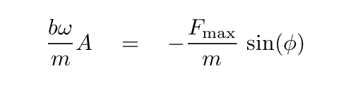
Let's get rid of all those exponential terms on the left-hand side by dividing both sides by eiφ.
Now, both sides contain real and imaginary quantities. In order for both sides to be equal, we must set the real portions equal to each other, and the imaginary portions equal to each other.
  Write one equation which contains only the real parts of this equation.

  Write another equation which contains only the imaginary parts.
Need a hint?
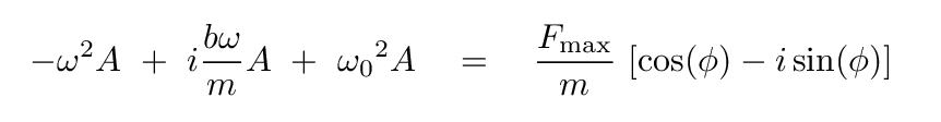
The real portion is

and the imaginary portion is
So, our guess for the solution, a simple sinusoidal motion as a function of time, will satisfy the differential equation, as long as these two equations hold true.
And so we end up with two equations for the two constants of integration: the amplitude A and the phase angle φ of the mass, relative to the driving motor. If we can separate them, and figure out amplitude and phase individually, then we'll finally be able to understand the nature of the system's response to the driving force.
Let's re-write these two equations so that the phase angle φ is on the left-hand side of each.
  Q:  Write each equation so the cos(φ) or sin(φ)
         term is on the left-hand side, alone,
         and everything else is on the right.
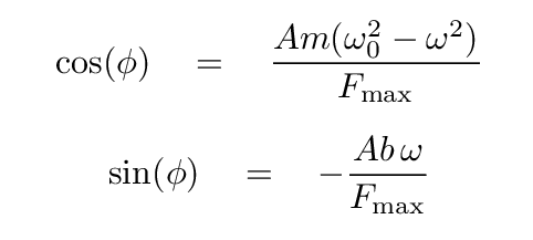
Hmmm. An expression for cosine of some angle which contains some stuff over Fmax, and an expression for sine of the same angle, which contains some other stuff over the same Fmax. That reminds me of forms I learned a long, long time ago.
                         adjacent
         cos(phi)  =  -------------
                        hypotenuse


                         opposite
         sin(phi)  =  -------------
                        hypotenuse

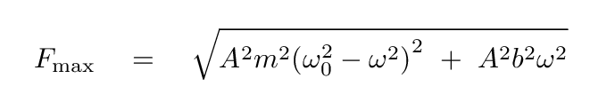
Aha! This is the key to determining the value of the amplitude A. First, we can write an equation for the value of the maximum force Fmax as a function of A alone ...
  Q:  Use the Pythagorean Theorem to write an expression
           for Fmax which does not contain
           the phase angle.
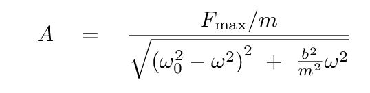
Now, we can take out the amplitude A ...
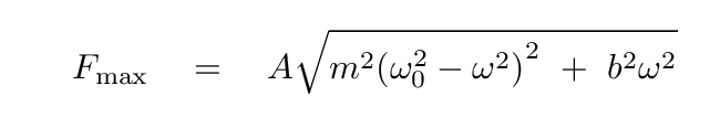
... and then re-write this so that we have an equation for amplitude A as a function of the driving frequency ω and other terms.

With one more tweak, we can put the equation into a form that is often found in discussions of forced harmonic motion.
We can use the same diagram to express the phase angle φ, too.
  Q:  Write an equation for the phase angle φ
          which does not contain the amplitude A.
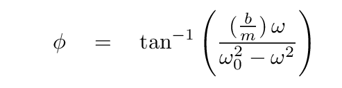
Notice that the formula above does not contain a negative sign inside the inverse tangent function, even though one would expect it, based on our derivation. This is a matter of convention: physicists have decided that this form better describes the fact that the driving force leads the object near resonance.
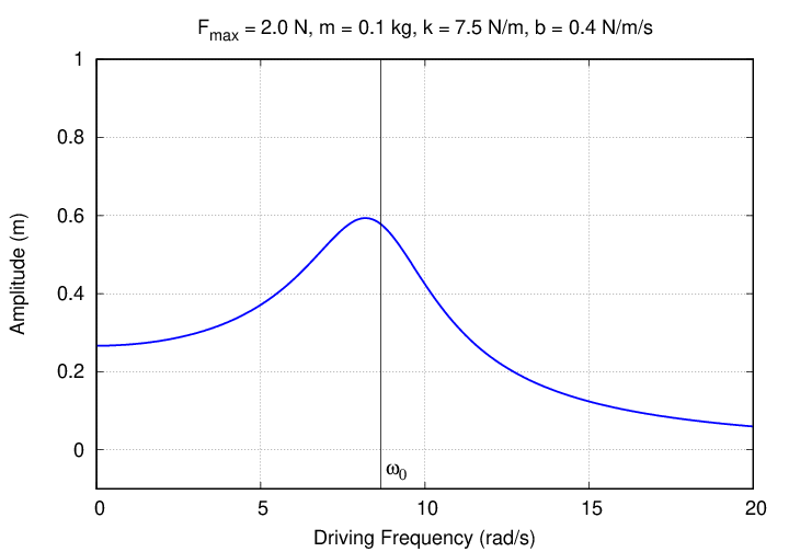
Let's look more closely at the amplitude as a function of frequency. The equation we've derived has a denominator with the sum of two terms: one contains the difference of the driving frequency ω and undamped frequency ω0 of the system. Since the amplitude will be largest when this denominator is smallest, it makes sense that the maximum amplitude occurs when the driving frequency is close to the undamped frequency ... as a picture will show clearly.

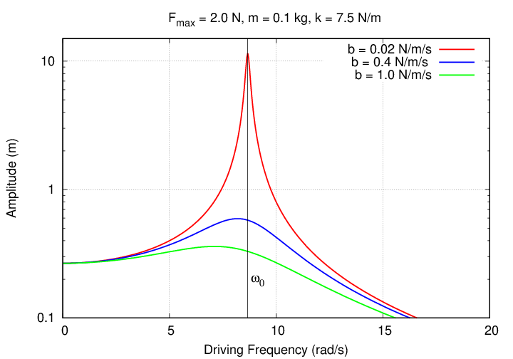
However, because that equation has a second term in the denominator,
the maximum amplitude does not occur EXACTLY at the undamped frequency ω0. The difference becomes easier to see if we increase the damping force.
The frequency yielding the maximum amplitude is slightly lower than the undamped frequency. How much lower? That sounds like a job for an extra credit problem ...
  Q:  Do you notice any other differences between the
           graphs for small damping (b = 0.02 N/m/s) and
           moderate damping (0.4 N/m/s)?
You should notice two other differences.
It may be hard to see these changes on a graph with a simple linear-linear scale ...

... so take a look at a graph with a logarithmic scale for amplitude.
By the way, we should check the numbers here.
  The graph above shows the results for a particular combination
           of parameters:

                  k       =   7.5 N/m

                  m       =   0.1 kg

                  Fmax     =  2 N

                  b       =   0.4 N/m/s


   Q:   What is the undamped frequency of the spring?


   Q:   If we simply pull the spring with a CONSTANT force of Fmax,
              how far SHOULD the spring stretch?


   Q:   Under a VARYING force of Fmax at the undamped frequency,
              how far DOES the spring stretch?
Huh? That seems strange. We'll investigate this mystery in our next class.
But let's finish today by looking at the behavior of the phase offset φ as a function of the driving frequency. Here's the formula we derived again:
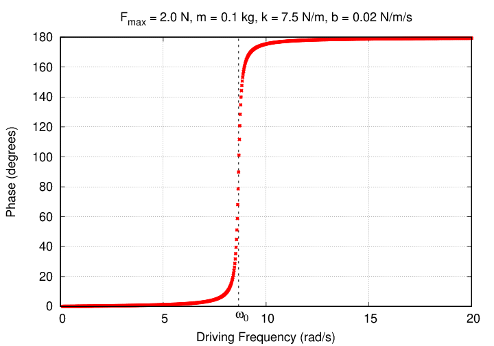
There are three regimes here:
Copyright © Michael Richmond.
This work is licensed under a Creative Commons License.