APOLLO Timing Scheme
The APOLLO timing scheme is a multi-layered system consisting of:
In reference to the above list, the task can be summarized as follows:
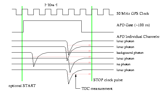
The high resolution timing scheme is pictured below.
The APD gate is opened for a certain number of clock pulses provided by the 50 MHz frequency reference. During this time (and only during this time), the APD array is biased beyond its breakdown voltage such that an individual photon can trigger an electronic avalanche, resulting in a negative-going pulse. These pulses trigger START events that are fed into the time-to-digital converter (TDC). After the gate closes, the next 50 MHz clock pulse is chosen to provide the STOP to the TDC.
The TDC is a Phillips Scientific 7186H 16-plex CAMAC unit, so that up to 16 APDs can trigger STARTs during the same interval. The clock pulse performs as a COMMON STOP for all channels. In the diagram above, only 6 channels are shown. One channel sees no event (no photon tripped an avalanche in that APD element). Another channel is hit by a background photon, out of step with the remaining four channels. A strong return from the moon would show up as a cluster of pulses all at about the same time. Of course, even a single lunar photon will be discernible as the real thing by its timing information alone---provided a handful of other photons are also detected within an observing session.
The TDC then measures the length of the pink arrows for each photon return, within a range of 0-100 ns, to a precision of about 15 ps (2-millimeters of one-way distance).
The ACM keeps a careful count of the 50 MHz clock pulses, so that the photon event can be referred to the time within the current second to very high precision. The ACM is additionally capable of requesting that a START pulse based on the 50 MHz clock be sent to the TDC. In combination with the STOP pulse, the TDC sees pulses separated by some precise multiple of 20.00 ns (within 10 ps), so that the TDC can be calibrated against an absolute source.
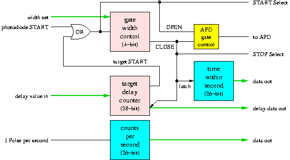
The above diagram shows the basic function of the ACM as related to running the time measurement. The photodiode kicks off the process, opening the APD gate. When the gate closes, various counters are latched. The calculated target delay is added to the value read off the target delay counter, and this value fed into the delay generator. When the delay counter reaches this value, the gate is again opened for the lunar photons. Additionally, counters keep track of the time within the second, and verify that no clock pulses are being skipped.
The above timing measurements are performed not just on the lunar photons, but also on "calibration" photons returning from a corner-cube retroreflector placed in the exit beam of the telescope. By knowing the precise location of the corner-cube with respect to the telescope's fixed point (the intersection of azimuth and elevation axes), one gets a measure of when the laser pulse left the (fixed point of the) telescope. This time stamp is referenced to the stable 50 MHz pulse train in exactly the same way as the lunar photons. The measurement to the moon then becomes a differential measurement of the roughly 2.5 second time of flight. As long as the 50 MHz source is accurate over this time period, the time measurement can be converted into a reliable distance. Phase noise analysis of the clock indicates a single-photon measurement accuracy of less than 1.5 millimeters. Multiple photons of course reduce the measurement error associated with the clock to an insignificant level.
There are some subtleties associated with squeezing the best possible timing performance out of the system. This more detailed discussion of the differential scheme explains some of these.