APOLLO Differential Scheme
The APOLLO system measures the time of flight of a photon from the fiducial fixed point of the telescope op to the effective center of the lunar retroreflector array. The standard technique for referencing the telescope fiducial is to place a corner-cube prism in the exit path of the laser, such that some small fraction of the outgoing beam is returned to the telescope and receiver. If the precise location of the corner-cube is known relative to the spatially fixed position within the telescope (typically the intersection of telescope mount axes), then the time offset can be manually removed.
In principle, one should arrange that both the path and signal strength of the so-called calibration return be as similar as possible to the lunar return. In APOLLO's case, a 25 cm corner cube intercepts 0.005% of the light emerging from the 3.5 m diameter primary mirror. At 3×10¹⁷ photons per pulse, this results in a 1013 photon return signal strength! After system inefficiencies and diffraction effects are taken into account, the expected number of detectable photons on the APD array is still a high 108 photons. We want to knock this down to about 2-5 photons per pulse.
Because we want to alternate between full sensitivity (for scarce lunar photons), and something about 107.5 lower (for calibration photons), we need a variable attenuator. For APOLLO, the rotating transmit/receive beam-switch (hereafter T/R switch) performs this function. The same high-reflectivity coating that directs the outgoing laser beam toward the telescope also prohibits returned light from finding the receiver (refer to optics layout). A second coating on the back of this mirror further attenuates any return to the 10-7 level.
Now that we have a calibration signal of appropriate strength, how best to extract the departure time of the laser pulse? One could simply take the mean of the reported photon arrival times (let's for now ignore the spatial offset between corner-cube and spatial reference point). As long as the photon number is small enough to be free from bias (or at least correctable), averaging is certainly a valid technique. But we can do better. Refer to the diagram below.

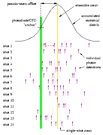
This diagram shows 14 sequential shots, based on a mean return rate of 4.5 photons per shot (higher than ideal for APOLLO). Assuming there are enough APD elements to accommodate this return signal without bias, the distribution of the entire ensemble will accurately reflect the time profiles of the laser, the APD jitter, the electronics and TDC jitter, etc. But on a shot-by-shot basis, the mean of the small handful of photons will not necessarily lie on top of the true mean (pink bars vs. yellow line). In general, the RMS scatter of the pink bars relative to the yellow line will be the standard deviation of the total time response profile divided by the square root of the number of photons detected in that particular shot.
Why tolerate this additional source of random error if you don't have too? In the single-photon regime, this source of error is the same for calibration and lunar returns (same laser pulse, same electronics, etc.), so that the RMS error of the time difference (which is what we care about) is sqrt(2)=1.4 times worse than the single-ended error.
We have another indicator of laser fire time, via the fast photodiode within the laser enclosure that signals to the ACM the start of the fire sequence. By locating the photodiode in a position where the integrated laser intensity falling onto the detector is very stable, and additionally employing a constant-fraction discriminator, one gets a very high resolution, repeatable measure of laser fire time. We have tested the photodiode/CFD/TDC time response jitter, and determined performance better than 20 ps RMS.
But the time of laser fire measured in this way can vary with respect to the time of departure of the pulse as temperature changes affect optical pathlengths, electronic signal delays, etc. The fact that the lunar photon arrival times are measured in a different way means that comparison to the photodiode-reported time of laser fire is not a differential measurement.
However, the offset between photodiode START and the APD-registered calibration photon time should not vary rapidly in time. That is to say, the offset between photodiode START (represented by the green line above) and the pulse centroid as it leaves the telescope is roughly a constant. The diagram suppresses the fact that the actual offset between these two is on the order of 100 ns (light travel time through telescope), but the concept is valid. Over timescales longer than about 5 minutes, we may see a drift in this offset. But for short times, we can use the photodiode START as an anchor against which to reference individual corner-cube-photon returns.
How does this play out in practice? The following sequence illustrates the process:
One can always check that no biases are being introduced by ignoring the photodiode information, using only the shot-by-shot means and swallowing the aforementioned sqrt(2) degradation in uncertainty. But this gets back to a true differential measurement against which the "anchor" technique can be checked.
It is also potentially very instructive to examine the time evolution of the offset between the anchor and the pulse center, and perhaps correlate this with environmental factors. There is also information in the pulse width and symmetry that may be monitored for changes. Because the only expected difference in pulse shape between the calibration and the lunar return is the lunar retroreflector array, the calibration pulse shape can be used to deconvolve the lunar response in order to more clearly ascertain the exact orientation of the array at the time of observation.