APOLLO Optical Design
The optics for APOLLO are very straightforward, and are pictured below (diagram produced by Sterling Fisher).
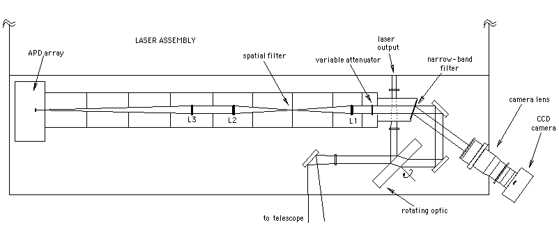
Shown here is the 1×4 foot strip on the optical bench adjacent to the laser (see the picture of the laser). The laser itself occupies the region above the diagram.
Following the laser output, the 9 mm output beam is expanded to about 17 mm, relfected off the rotating mirror (transmit/receive switch, or T/R switch), expanded into an f/10 beam, and directed toward the telescope port.
Inbound light is collimated to 20 mm, passes through the T/R switch, and is folded iup and into the receiver. At the receiver entrance is a narrow-band filter that permits only the appropriate green wavelength to pass, and sends the rejected light to a CCD camera. Within the light-tight receiver tube is a variable attenuator (PLZT), a spatial filter to further reduce background light, various baffles, and finally the APD. L1 and L2 are achromats, but optical performance is perfectly acceptable with all other lenses as singlets.
The APD array itself has a lenslet array in front of it (at the focal plane), with 100 µm spacing and 0.5 mm focal length, forming a pupil image on each of the APD array elements.
Both the laser beam expander and the f/10 diverging/collimating lens utilize linear motion stages permitting adjustment of laser beam collimation and overall system focus. Additionally, one of the fold mirrors preceeding the receiver is tip-tilt adjustable allowing real-time co-alignment of the laser bean and the receiver. For satellite ranging, these need to be intentionally offset due to relativistic velocity aberration. For the moon, this is slightly less than one arcsecond, though worth controlling. Because the CCD and receiver are permanently aligned with respect to each other, a unique pixel on the CCD array can be associated with the center of the APD field, so that the CCD becomes a primary tool in target acquisition.
The T/R switch is a large, flat optic spinning at 20 Hz (1200 RPM). The rate can be adjusted slightly (and dynamically) to guarantee that lunar returns arrive 180° out-of-phase with the laser fire. The T/R switch is mostly clear, and anti-reflection coated, but has a small patch of high-reflectance multi-layer dielectric coating for reflecting the laser beam. This patch, in conjunction with a similar patch on the back side (the side away from the laser) provide 7 orders-of-magnitude of attenuation for the receiver, so that when the laser fires the receiver is shielded from backscatter along the optical train. This also reduces the calibration signal from the corner-cube prisms within the telescope to the few-photon level at the APD array.