APOLLO Mechanical Scheme
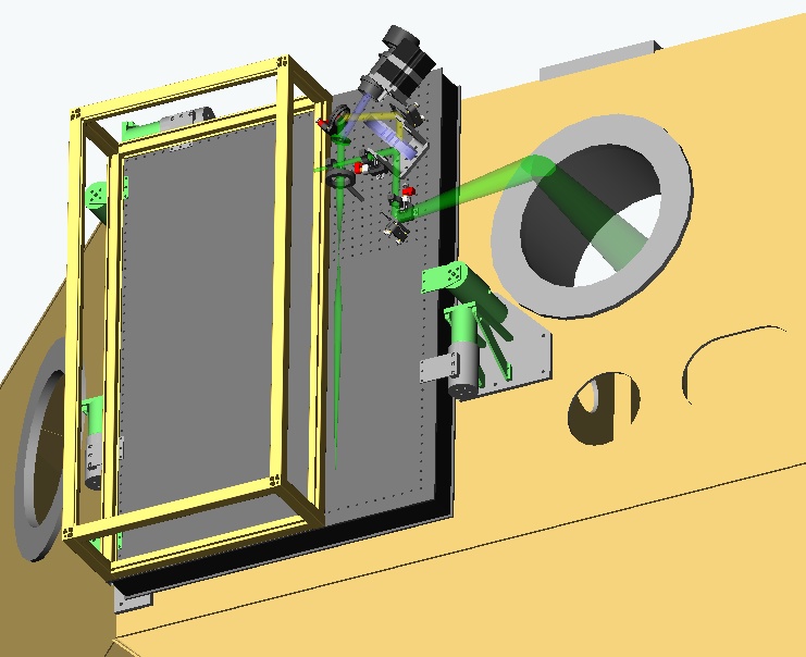
The laser bench will mount kinematically onto the back port of the telescope as indicated below. The kinematic scheme is necessary because the laser bench will be held at a constant temperature, while the telescope experiences large swings in temperature. The relative thermal expansion would stress the optical table if a rigid mount were employed.
The large tan structure is the 3.5 meter telescope primary mirror cell. The laser is mounted on the back plate, whose orientation is horizontal when the telescope is pointed at the horizon, and vertical when the telescope is at zenith. The sky direction in this view is up.
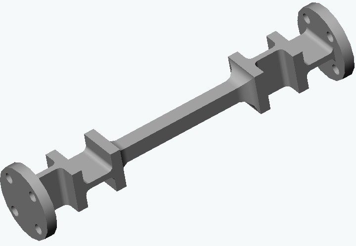
The mounting scheme consists of six flexures mounted in a 3-2-1 configuration. Each flexure provides a constraint in one dimension only--along its long axis. The picture below shows the appearance of one of the flexures.
The flexures are housed in the green and gray nested tubes seen in the picture. Three legs keep the optical bench parallel to the telescope plate, two prevent translation in the skyward direction, and the last keeps the laser bench from rotating. The three legs support most of the weight when the telescope points to low elevations, and the two side-mounted flexures hold the weight when the telescope is pointed toward the zenith.
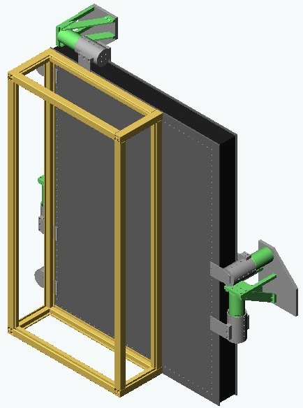
The tubes containing the flexures provide safety in case the flexures should mechanically fail. The inner and outer cups don't touch unless this happens, but offer support for the laser bench in this event.
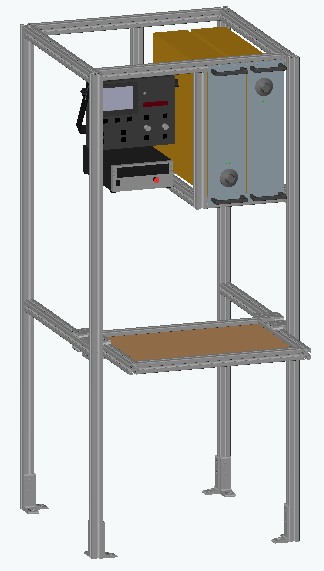
The laser itself is built within the gold frame on the left side of the bench. A box will enclose the entire laser bench for thermal and stray light control.