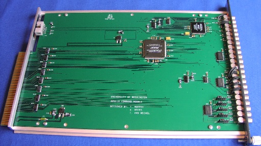
APOLLO Command Module Photo

A view of the ACM board, installed in its mechanical housing that slides
into the CAMAC crate. The board itself is an 8-layer design, with generous
ground planes and minimal signal-line overlap. From left to right are:
- The CAMAC double-sided edge-connector,
- Reprogramming port (upper-left) for reprogramming PLDs,
- input/output buffers,
- voltage regulators (lower-left and upper-center),
- the large PLD handling the CAMAC interface (commands, data I/O),
- the smaller (and faster) PLD for timing control and signal input/output,
- the front panel, with 22 LEMO connectors and a few LEDs.
APOLLO Command Module
APOLLO Apparatus Page
APOLLO Main Page

