May 19, 2016 UT: Polar alignment and pretty pictures of Jupiter and the Moon
Michael Richmond
May 19, 2016
On the nights of May 13/14 and May 18/19, 2016,
I adjusted the polar alignment of the Meade LX200 12-inch
telescope in the dome at the RIT Observatory.
My goal was to improve the tracking performance,
so that we could take longer exposures without guiding.
This page is largely a summary of the notes
I took during the procedure,
which I hope will make it go more smoothly
in the future.
I also took a few pretty pictures of Jupiter
and the Moon, just for fun.
Preliminaries
On May 13/14, I used the usual arrangement of
CCD + filterwheel + Off-Axis-Guider (OAG).
But after that, I sent the filterwheel mechanism
back to the manufacturer for repair.
It turns out that I don't have the proper parts
to connect the CCD to the OAG directly,
so on May 19,
the arrangement was just CCD directly mounted
to the telescope's focuser.
This had two consequences:
first, I had to figure out the proper orientation
of the camera,
and second, I needed to modify the focus of the
telescope because the focal plane was now
considerably closer to the mirrors.
The orientation is simple: to end up with the
usual North up, East left arrangement without
changing any parameters in MaximDL,
one must rotate the CCD camera so that
the yellow "RIT" label is to the South
(that is, close to the telescope pedestal when in the park position).
The change in the focal plane position was very
roughly 2.3 inches closer to the mirrors,
based on the
ATIK system chart
schematics.
In order to move the focus in this direction,
I discovered that
turning silver focus knob CW moves focus toward mirrors.
Polar alignment notes
There are a number of good guides to aligning a telescope
to the pole using the "drift method"; for example,
One can summarize the two steps of the method
(adjusting the azimuth and altitude of the telescope's polar axis)
as follows:
 To adjust    point      if star   then axis     turn LX200       on TV screen,
             telescope    drifts     is           knob            stars will
-----------------------------------------------------------------------------

 altitude    to East      South      too low      CCW to raise     jump up (North)

                          North      too high     CW to lower      jump down (South)


 azimuth     to South     South      too East     CCW to go West   jump right (West)

                          North      too West     CW to go East    jump left (East)


-----------------------------------------------------------------------------
My typical procedure was as follows:
- start a sequence of ten images: 5 seconds exposure time,
followed by 30 seconds of delay
- measure position of a star in first image in sequence
- measure position of a star in tenth image in sequence
- compute amount of drift in pixels (binned 2x2,
so 1 binned_pixel = 1.32 arcsec)
- if desired, divide by elapsed time, approx 360 seconds
(nine images at approx 40 seconds each)
I was able to compute very, very roughly the response of the
drifting behavior to the position of the axis-adjustment
knobs.
- when adjusting altitude
- rotating knob by 1 "bump"
results
in drift rate of about 6 binned_pix = 8 arcsec in 360 seconds
The picture below indicates what I mean by a "bump" on the
axis adjustment knob (yes, the picture shows an azimuth
knob, rather than an altitude knob, but the structure is the same)
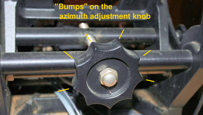
Image courtesy of
Dale A. Chamberlain's Guide to Polar Alignment of Meade LX200GPS Telescope
- when adjusting azimuth
- moving knob by 1 full turn leads to a change
in drift rate of about 15 binned_pix = 20 arcsec in 360 seconds
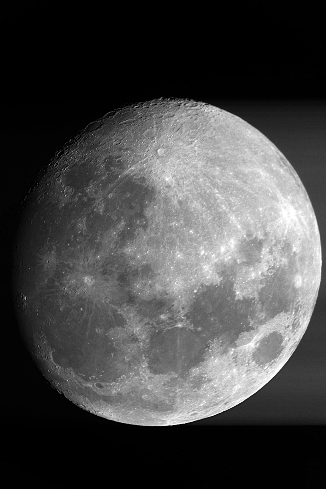
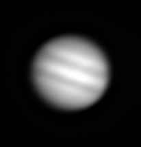
Pretty pictures of Jupiter and Moon
As I waited for the sky to darken, I took some pictures
of Jupiter and the Moon, just for fun.
Even though I used an off-axis mask to decrease the
amount of light entering the telescope
(the mask has a circular aperture about 5 inches
in diameter),
the lack of any filters
meant that I could barely acquire data
without saturating the
detector.
I used exposures times of 0.02 seconds for Jupiter,
and 0.005 seconds for the Moon.
After bias-subtraction and flatfielding,
I tried this and that to make a pretty image.
I grabbed a copy of
Registax
and used it to stack 17 images of Jupiter.
Because the 2x2 binned plate scale is so poor,
1.3 arcsec/pixel,
the image doesn't show much:
Our images of the Moon were a bit nicer.
The Moon just barely fits onto the chip.
I chose the sharpest image in a set of 10
and did just a little processing to make the version
below.
The "ghost" faintly visible to the right
is an artifact of the charge-transfer process,
noticable due to the very bright nature of the target here.
Click on the image below for the full-resolution version.

Last modified 5/19/2016 by MWR.