
KIWI-OSD
Video overlay of GPS precision timestamps
Matt Montanaro
Dr. Michael Richmond
Rochester Institute of Technology
February 2005
Contents:
Purpose of KIWI OSD 3
Contact information 3
Parts List 4
Circuit Diagrams 5,6
IC Pin Assignments 7
Garmin GPS 16-HVS 8
Power Supply 10
Construction 11
Using the KIWI OSD 12
INFO Switch 13
Example of KIWI OSD in action 14
Epilogue 16
Purpose of the KIWI-OSD:
The KIWI-OSD device timestamps video frames to millisecond precision. A video feed from a source (video camera) is sent into the KIWI. A timing signal from a GPS receiver is used to timestamp the incoming video with the Universal Time (UTC) signal. The video is then outputted to a receiver (TV, VCR, etc.).
KIWI-OSD Video In Video Out

GPS

Geoff Hitchcox contact information:
Geoff is the inventor of the KIWI-OSD. His can be contacted at: kiwi_36_nz@yahoo.co.nz
*** The PIC16F628-20 Integrated Circuit chip must be programmed by Geoff. He installs his KIWI OSD software on it and will mail it to you (see diagram page 5).
*** The GPS must be configured to emit the proper timing signal. Geoff has a nice program that he can email you that does this (see page 9).
Geoff’s KIWI-OSD webpages:
http://www.geocities.com/kiwi_36_nz/kiwi_osd/kiwi_osd.htm
http://www.geocities.com/kiwi_36_nz/kiwi_osd/example.htm
Parts List:
Name Category DigiKey Part# Quantity
LM1881 DIP-8 IC chip LM1881N-ND 1
PIC16F628-20 DIP-20 * IC chip PIC16F628A-I/P-ND 1
74HC74 DIP-14 IC chip 296-1602-5-ND 1
74HC00 DIP-14 IC chip 296-12769-5-ND 1
18-pin DIP socket DIP socket ED58183-ND 1
14-pin DIP socket DIP socket ED58143-ND 2
8-pin DIP socket DIP socket ED58083-ND 1
680 kΩ Resistor 680KEBK-ND 1
10 kΩ Resistor 770-103-R10K-ND 1
22 Ω Resistor 22H-ND 1
1 kΩ Resistor 1.0KEBK-ND 1
1 MΩ Resistor 1.0MEBK-ND 1
100 Ω ** Resistor 100QBK-ND 1
10 kΩ ** Resistor 10KEBK-ND 1
1 kΩ Trimpot Potentiometer 31G13-ND 1
0.1 μF 16V Capacitor BC1084CT-ND 6
15 pF Capacitor BC1003CT-ND 2
1N914 Diode 1N914BCT-ND 2
NPN 2N2222 (TO-92) Transistor P2N2222AOS-ND 1
RCA video jack Connector CP-1403-ND 2
Power Jack 2.1mm Connector SC1152-ND 1
Crystal 16Mhz Crystal 300-6034-ND 1
Push Button Switch Switch EG1101-ND 1
Switch cap, square Switch EG1192-ND 1
Other parts:
2” x 3” x 6” Plastic Case Enclosure Radio Shack 1
Proto-board Prototype board Local electronics store 1
8-pin RJ-45 jack Connector Local electronics store 1
9-pin DB-9 Serial Connector Local electronics store 1
* Must have KIWI software installed (see page 3)
** Required for Voltage Divider (see page 10)
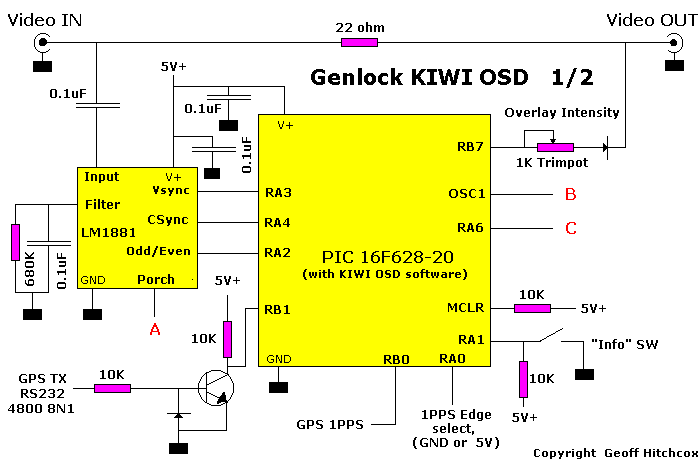
Pin Assignments for KIWI OSD
LM1881
Pin connects to
---------------
1 pin 3 of 16F628 (Csync)
2 Composite video input via 0.1uF
3 pin 2 of 16F628 (Vsync)
4 GND
5 pin 10 of 74HC74 (PORCH) [ A ]
6 to filter using 680K and 0.1uF
7 pin 1 of 16F628 (Odd/Even)
8 +5 Volts
16F628
Pin connects to
---------------
1 RA2 to pin 7 of LM1881 (Odd/Even)
2 RA3 to pin 3 of LM1881 (Vsync)
3 RA4 to pin 1 of LM1881 (Csync)
4 MCLR to 10 K and optional RESET switch
5 GND
6 RB0 to 1PPS
7 RB1 to RS232 via transistor inverter
8 not used
9 not used
10 not used
11 not used
12 not used
13 RB7 (overlay video out)
14 +5 Volt
15 RA6 to pin 11 of 74HC74 [ C ]
16 OSC 1 CLKIN from pin 6 74HC00 (Gated 16 MHz CLOCK) [ B ]
17 RA0 - jumper to GND for 1PPS LO to HI UTC transition (most common)
- jumper to +5V for 1PPS Hi to Lo UTC transition
18 RA1 connects to "info" push button switch
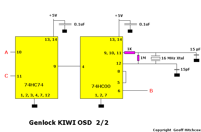
74HC00
Pin connects to
---------------
1 GND
2 GND
3 not used
4 to pin 9 of 74HC74
5 to pin 8 of this IC
6 to pin 16 of 16F628 [ B ]
7 GND
8 to pin 5 of this IC
9,10,11 connected together to XTAL
12 from XTAL
13 + 5 Volts
14 + 5 Volts
74HC74
Pin connects to
---------------
1 GND
2 GND
3 GND
4 GND
5 not used
6 not used
7 GND
8 not used
9 to pin 4 of 74HC00
10 to pin 5 of LM1881 (PORCH) [ A ]
11 to pin 15 of 16F628 RA6 [ C ]
12 GND
13 + 5 Volts
14 + 5 Volts
Garmin GPS 16-HVS:
Power requirements: Voltage: 6 – 40 Vdc unregulated
Current: 100 mA @ 6 Vdc
65 mA @ 12 Vdc
28 mA @ 40 Vdc
RJ-45 Connector:
Pin 1 (Red) - Power (+)
Pin 2 (Black) - Ground [Power (-) and Data Return]
Pin 3 (Yellow) - Remote Power On/Off
Pin 4 (Blue) - Port 1 NMEA 0183
 Pin
5 (White) - Port 1 NMEA 0183
Pin
5 (White) - Port 1 NMEA 0183
Pin 6 (Gray) - Pulse Per Second Output
Pin 7 (Green) - Port 2 RTCM SC-104
Pin 8 (Violet) - Port 2 Data Output
RJ-45
Connector (head on view)
Garmin GPS 16-HVS manual:
http://www.garmin.com/manuals/GPS17N_GPS16_17NSeriesTechnicalSpecification.pdf
Configuring the GPS:
The Garmin GPS must be configured using a PC computer before using it with the KIWI. A cable must be constructed to connect the RJ-45 connector of the GPS to the computer’s serial port. The diagram below shows the wiring for the cable:
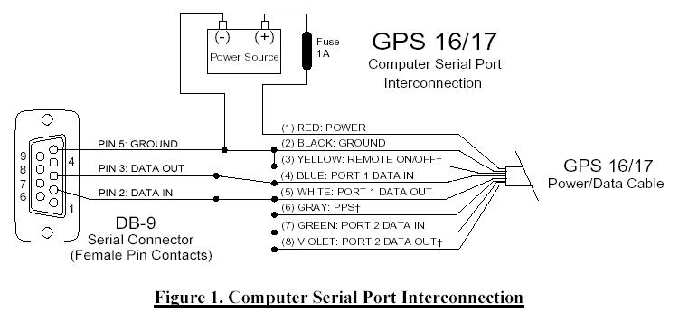
The power source can be any DC supply between 6 and 40 volts. Once the PC and GPS are connected and powered up, the GPS can be programmed. The purpose of configuring the GPS is to enable the 1PPS signal and to only allow the NMEA sentences GGA and RMC that are needed my the KIWI. Geoff Hitchcox emailed me the program (SNSRCFG.exe) and configuration file (KIWI_OSD.cfg). (See page 3 for his contact information).
Software Settings:
Run the SNSRCFG.exe program from Geoff
Select “GPS 16/17” for the Garmin Base Model
Comm Menu > Setup → Select COM1 serial port and Auto Baud Rate
File > Open → select KIWI_OSD.cfg → Open
Config Menu > Sensor Config → Input your latitude and longitude
Comm Menu > Connect
The computer will attempt to connect to the GPS
After successful connect: Config Menu > Send config to GPS (this will upload the .cfg file settings to the GPS)
All done! Close program and disconnect the GPS.
Connecting the GPS to KIWI:
GPS Pins:
Pin 1 to Power (+)
Pin 2,3 to KIWI ground
Pin 5 to 10k resistor “GPSTX NMEA 4800 8N1”
Pin 6 to Pin 6 of the PIC16F628-20 “GPS 1PPS” RB0
Note: Pin 17 of the PIC16F628-20 (RA0) “1PPS Edge Select” connect to ground
Power Supply:
I used a Vernier AC Adaptor Class 2 Transformer
Input: 120V AC 60Hz 8W
Output: 6V DC 600mA
Connector: 2.1mm jack
The KIWI requires 5V of DC power. The GPS can take anything from 6V to 40V. So, since the power supply outputs 6V, I use a simple voltage divider to get the 5V I need to the KIWI.
Construction:
The KIWI circuit was constructed on a 2½” x 4½” proto-board. Solid core wire was used for most connections. Twisted core wire was used for the GPS RJ-45 connection. The picture below shows the completed circuit:
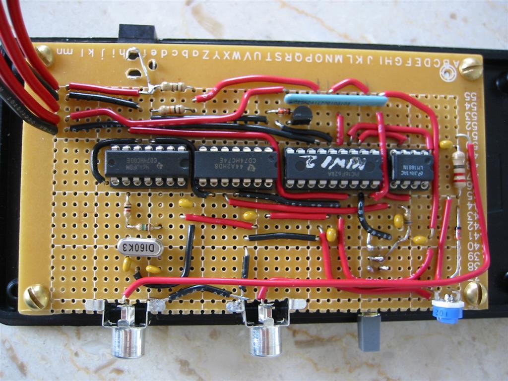
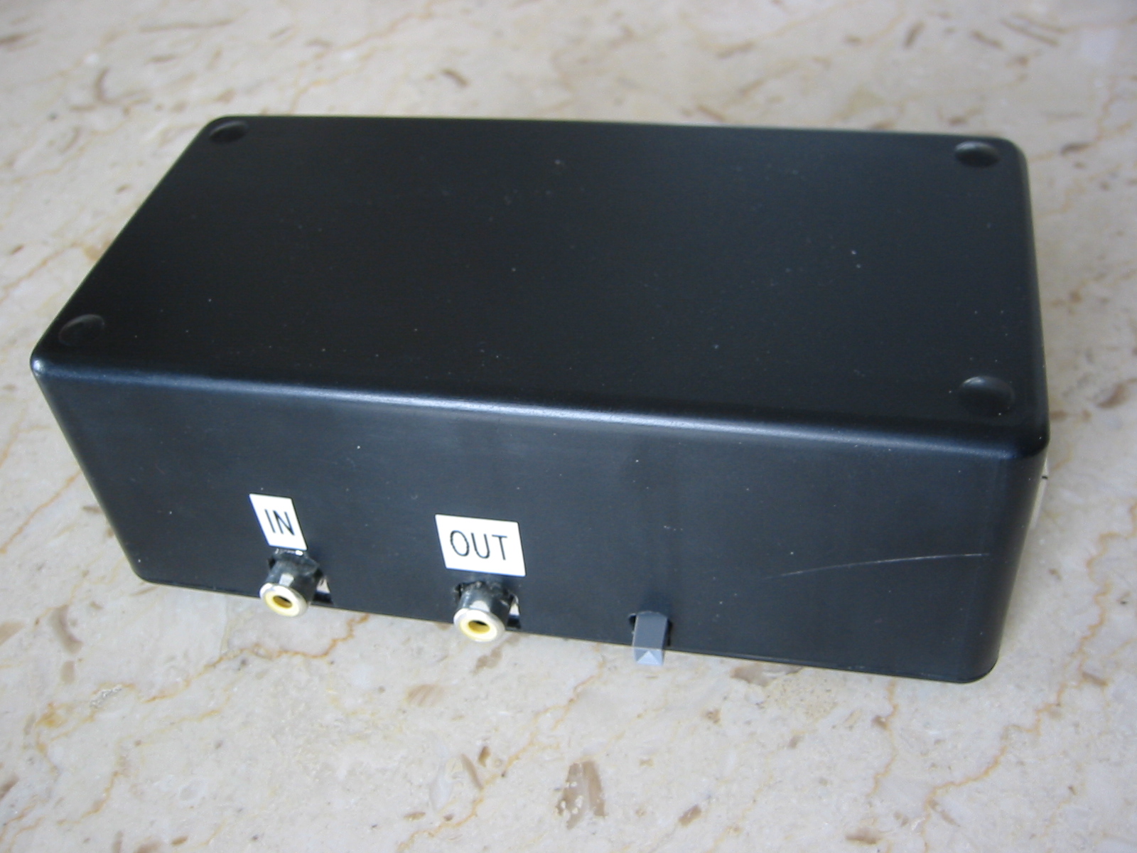
The circuit is mounted into a plastic enclosure box.
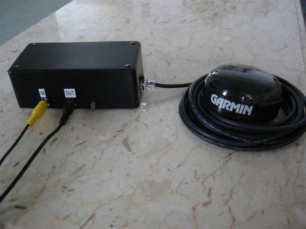
Using the KIWI OSD:
KIWI connected to video in and out and to the GPS:
Initial Setup:
Turn on the power to the KIWI
Connect the video input and the video output
Connect the GPS
Display:
The onscreen display will display “RS232 or 1PPS Absent” at first
Then “KIWI OSD V2 FIXWAIT” will be displayed while the GPS attempts to lock onto satellites.
The latitude and longitude will then be displayed followed by satellite information
UTC date is displayed
“KIWI OSD V2 FIXWAIT 1… 2… 3… … 9”
UTC time, end of frame time, start of frame time, counter displayed
This is a picture of the official US time from the NIST webpage with the KIWI onscreen display overlaid:
NIST Time KIWI OSD
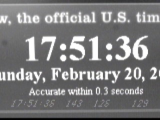


UTC
time HH:MM:SS Field
Counter End
of Field time (ms) Start
of Field time (ms)
The bottom of the video screen has this format:
HH:MM:SS EEEE OOOO FFFFFF
where:
HH:MM:SS = Hours, Minutes, Seconds UTC time
EEEE = End of Field time (in milliseconds)
OOOO = Start of Field time (in milliseconds)
FFFFFF = Contiguous field count since initial GPS sync
Note about the INFO Switch:
Geoff notes the function of the INFO switch on his webpage:
After you have finished the timing run, pressing the "info" switch requests that Kiwi OSD wait for the first valid GPS fix - and then compare its internal clock to the GPS. If they agree, a message "PREVIOUS TIMES OK" is displayed on screen. If GPS does not agree, "ERROR: USE FIELD COUNT" is displayed, alerting the user that there has been a previous GPS glitch, and to use the video field count to extract timing information.
Pressing the "info" switch after reading the above summary, gives the OSD chip a RESET, and so another timing run is started.
Example of KIWI OSD in action:
I attempted to measure the acceleration due to gravity with the aid of the KIWI. I took a video of a ball dropped from a certain height. The KIWI allowed me to measure precisely when the ball was dropped and when the ball hit the ground. By knowing the free fall time, the gravitational acceleration can be calculated:
 Video
frames of the ball drop:
Video
frames of the ball drop:
Frame 1 Frame 2
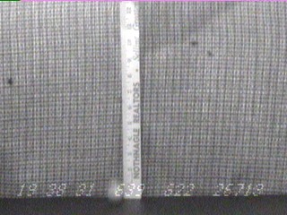
Frame 3 Frame 4
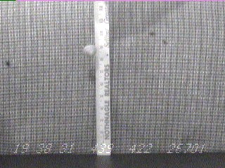
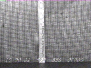
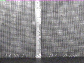
The pictures may not be clear to you. Here is the time for each frame:
Frame 1: 19 38 31 439 422 26701
Frame 2: 19 38 31 506 489 26705
Frame 3: 19 38 31 572 556 26709
Frame 4: 19 38 31 639 622 26713
The distance of the fall is 8 inches or 0.2032m (The distance is measured from the top edge of the ball). In frame #1, the ball is stationary throughout the exposure. In frame #2, the ball has begun to fall. Therefore, I will say the start of the fall occurred at the end of frame #1, so at 19:38:31.439
In frame #4, the ball has made contact with the ground. It looks to me to be at the end of the exposure. I will use the end time for frame #4 as the end of the fall, so at 19:38:31.639
The free fall time of the ball is then: 0.639s – 0.439s = 0.200s
The gravitational acceleration is then calculated by:
The uncertainty in the timing of the frames is half the exposure time. So, for frame #1 the start time is 422ms and the end time is 439ms so the uncertainty is 9ms
So my calculation for the uncertainty in g is:
g = (10.16 ± 0.9) m/s2
The accepted value for g is 9.81 m/s2
My value differs with the accepted value by 3.5%
Although I could have gotten closer to the accepted value by having a greater distance for the ball to free fall, my quick measurement and calculation worked fairly well.
Epilogue:
This manual is meant to give a summary of my work in building this device. I tried to explain the function and use of the KIWI OSD as straight-forward and simple as I could. For a much more detailed explanation on the operation of the KIWI OSD, please visit Geoff Hitchcox’s webpages. He is also extremely helpful through email (see page 3).
Special Thanks to
Geoff Hitchcox
Dr. Michael Richmond
Dr. Linda Barton
Bill VanDerveer