We've had some problems with the heating system for the house at the observatory. A boiler heats water in the basement, and a pump then distributes it to baseboard heaters around the house. Last night, the system stopped working -- that was the third time it's happened in the past two years.
Fortunately, FMS came out quickly and diagnosed the problem: a leaking pump caused too little water in the system, dropping the water pressure and leading to a shutdown. This morning, one of their workers came to examine the pump. I was there by coincidence and watched him at work. I took some pictures to explain how to deal with the problem if it should recur (but the plan is to replace the pump, so it should not be necessary).
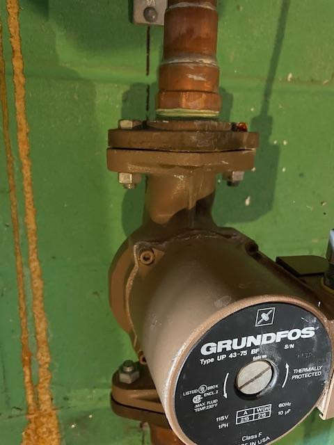
The picture below shows the pump. You can see a wet spot on the bottom of the flange where the pump is joined to the pipes above it. That's the source of the leak.
When enough water has leaked, the water pressure drops from its nominal level of about 25-28 psi to just 5 or 8 psi; at that point, the system notices the lower water pressure and shuts down. An error message of "E302" is shown on the main system's display, a blue LED display:

The current water pressure value can be read on a gauge below and two the left of the main system. The picture below shows a proper value of about 30 psi.

In order to insert more water into the system, one can release a level mounted on a pipe up near the ceiling of the basement, up above all the pumps and other equipment. See the circular item in the middle of this pipe?

On top of that item is a level shaped a bit like the blade of a mousetrap. If one lifts the level, pulling it up and rotating it to the right, water will flow into the system.

Watch the pressure gauge, and close the level to stop the inflow of water when the pressure reaches 25-28 psi.
Then push the reset button on the main system to cause it to reboot. When it finishes, the error message "E302" should disappear. In its place, the blue LED display will alternate between two values: the temperature of the water, and the pressure of the water. In the example below, it is showing the pressure: 28 psi, a good, normal value.
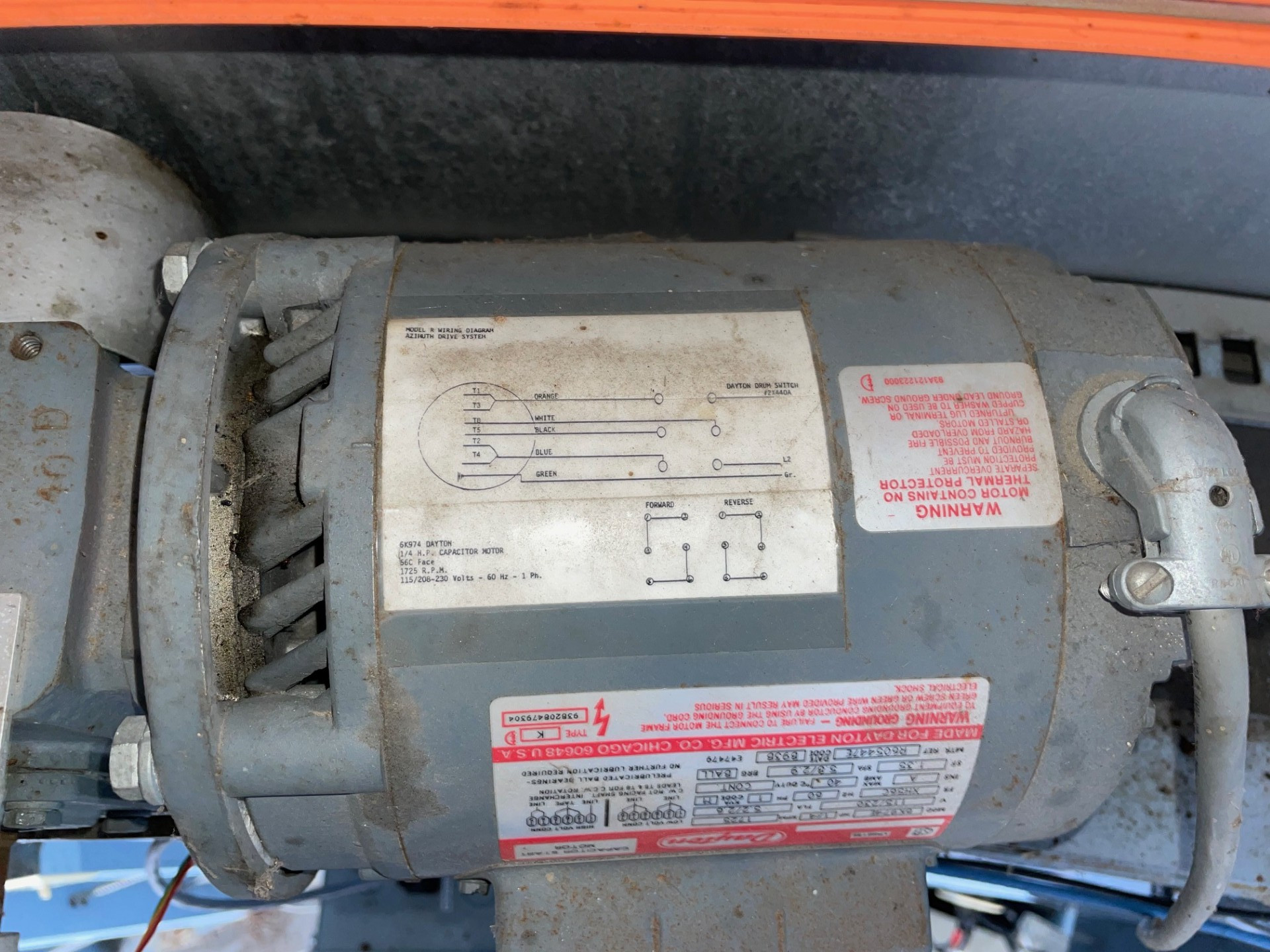
We are thinking of modifying our system for controlling the dome of the 12-inch telescope. At the moment, one must manually push toggle switches to rotate the dome, and to raise/lower the dome's shutter. We'd like to allow these functions to be controlled by a computer. As part of that effort, I took pictures of some of the hardware, to show to various vendors.

Here's a closeup showing the writing clearly:

The primary controls are provided by a box on the wall, installed by Autoscope many years ago. The box has toggle switches on its left side:

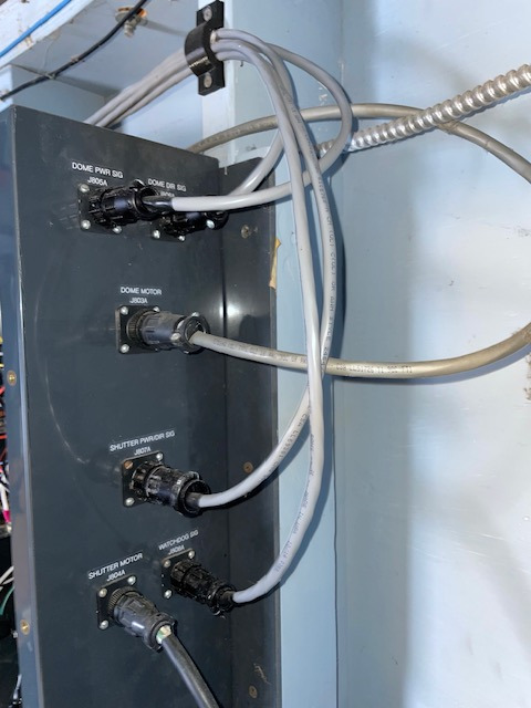
The box has cables running to various motors on its right side:
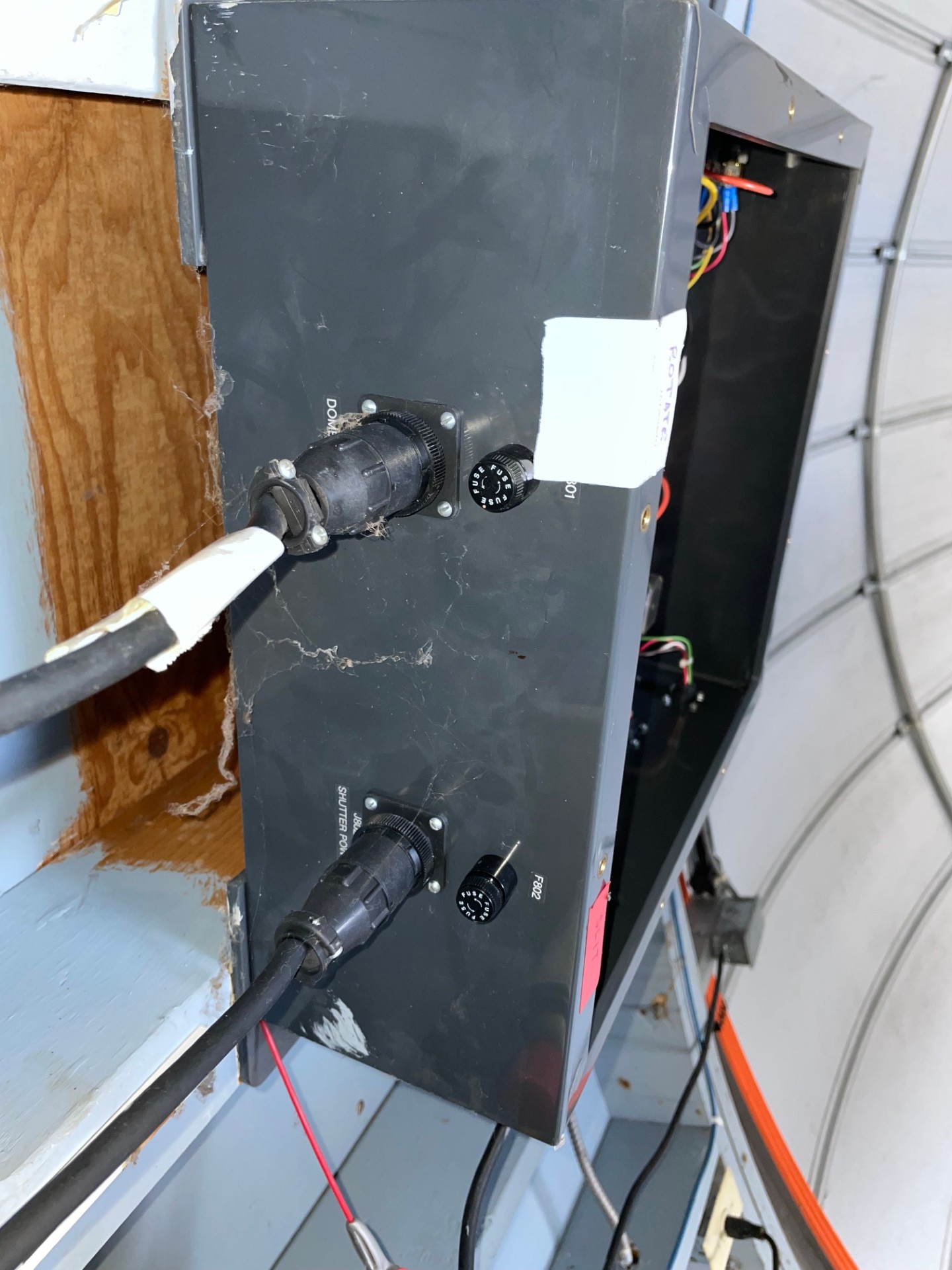
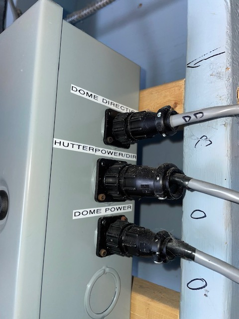
On the bottom of the box are cables for dome rotation (on the left) and dome slit open/close (on the right):

Taking the cover off the box, one can see the wiring. First, the left side (where the toggle switches are):
The right side (where the cables running to motors are):

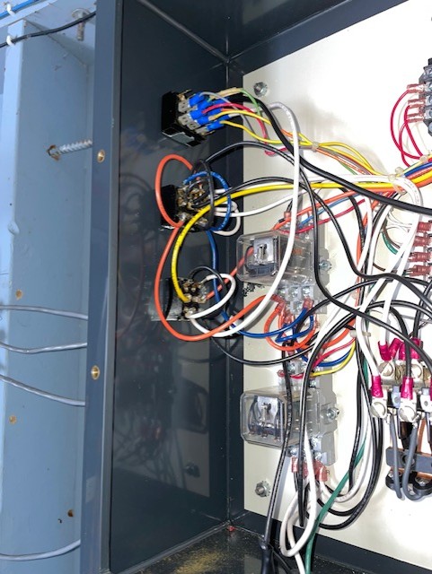
Finally, the interior of the box, all at once:

Several years ago, some engineering students put together their own system for controlling the dome's motors from a computer. Alas, we can use the software which ran their system due to an expired license, so their system is currently inactive. The hardware, however, is still all connected; we've just switched it to allow manual control.
In order to send signals to the motor which lifts/lowers the dome slit, this interface box sits near the base of the slit.
 The students' project is inside a second, smaller box
hanging on the interior wall of the observatory.
Its right side has wires running to the Autoscope box:
The students' project is inside a second, smaller box
hanging on the interior wall of the observatory.
Its right side has wires running to the Autoscope box:
The left side of this box has wires for control, leading back to the computer.

The top of the student box has wires running to an encoder on the shaft of the motor which rotates the dome.


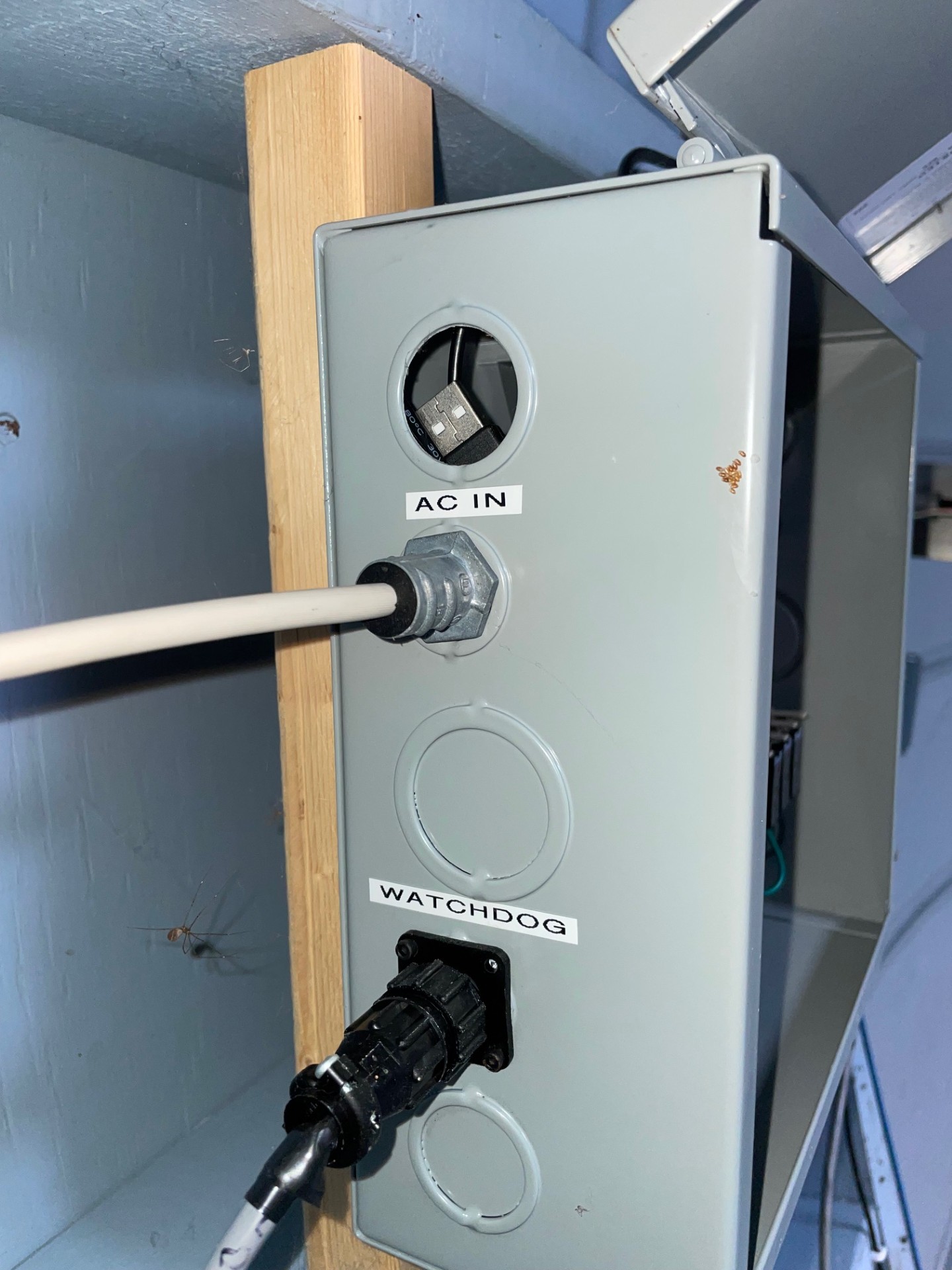
The bottom of the student box has wires for power and a watchdog timer.
Inside the student box are a cleanly laid out set of relays (I think):


In order to send signals to the motor which lifts/lowers the dome slit, this interface box sits near the base of the slit.
There is a panel at the base of the slit which, by default, moves with the shutter as it opens. When fully opened, this panel sits at the zenith, blocking views of the sky directly overhead. The panel can be disconnected from the shutter by manually lifting a spring-loaded latch:

However, we don't plan to automate this particular item in the near future: a person will have to latch or unlatch the lower panel, manually.
Last modified 2/11/2025 by MWR.