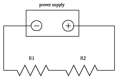
Figure 1.
Determining the effect on a circuit of applying a voltmeter to that circuit, and comparing the effects of two different kinds of voltmeter.
To see how measuring devices can change the very quantities they are designed to measure.
Cutnell and Johnson 20.6, 20.7, 20.8, 20.10 and especially 20.11.
Meters are designed to measure currents and voltages in circuits without changing the values of these variables in the circuit. Thus, since voltmeters are connected in parallel to a circuit element, we want the meter's resistance to be so large that a negligible fraction of the current in the circuit passes through it. Similarly, an ammeter is connected in series with a resistor in order to measure the current through the resistor. In order to keep the potential difference across the ammeter insignificant, it must have a resistance that is so small that it is negligible compared to the other resistances in the circuit.
Ideal voltmeters would have infinite resistance. Real voltmeters have finite resistance; thus, they may affect the circuit to which they are connected and give inaccurate readings.
This experiment involves two steps. In each step, you must build a circuit as shown in Figure 1 below.

Figure 1.
One of the pieces of equipment in your kit this week is a circuit board with 2 pairs of resistors. One pair consists of two 1,000 Ohm resistors connected in series. The other pair consists of two 100,000 Ohm resistors connected in series. Use first one pair, then the other, as described below.
There are two different voltmeters in your kit. One is a digital meter, made by Fluke. Set the knob on the digital meter to the position labelled with a V with a solid bar over it -- that causes the meter to measure voltage in a circuit with direct current. The other meter, made by Simpson, is an analog device: you must read voltages by noting the position of a needle which moves in front of a graduated dial. To use the analog meter, do the following:
The digital meter has a resistance of 10,000,000 Ohms. The resistance of the analog meter depends on the voltage of the current passing through it:
resistance of analog meter = 20,000 Ohms per volt
What is the resistance of the analog meter in your circuit?
First, you must set the power supply so that it provides exactly 10 Volts. Use the digital voltmeter, connected directly to the terminals of the power supply, to set the power supply as close to 10.00 volts as you can. Do not modify the power supply during the rest of this experiment.
Step I. Using 1,000 Ohm resistors
Step II. Using 100,000 Ohm resistors
Repeat items 2-11 with this setup.
When you have finished making all measurements, turn the control knob of the digital meter to the "Off" position.
Which meter do you consider better, and why? Use the above results in your explanation. You may include other factors, too, such as ease of use, size, weight, etc.