Resistors in Series and Parallel
Purpose
To see how the theory of DC circuits applies to reality,
and to practice analyzing combinations of circuit elements
in series and parallel.
What's the Point?
Real electrical devices consist of many elements (resistors,
capacitors, diodes, batteries, etc.) connected in complicated
ways. Fortunately, there are a few simple rules -- Kirchoff's Laws --
which allow one to break a complicated circuit into simpler and
simpler pieces, and figure out what happens within each piece.
If you understand the difference between connections in series
and in parallel, and if you know Kirchoff's Laws, you
can work your way through any DC circuit.
Background Reading
Cutnell and Johnson, Sections 20.6 - 20.10
Equipment
- breadboard
- jumper wires
- power supply
- 2 patch cords
- multimeter with hook clips
- at least 6 resistors of each type:
- brown black brown gold
- red red brown gold
- orange orange brown gold
- grey red brown gold
Procedure
- Examine the breadboard
- Connecting a single resistor to a power supply with long
pieces of wire is easy. But if you try to connect more
than four or five elements, you soon end up with a mess of
tangled cords. The breadboard provides a neat,
clean way of organizing and connecting elements.
Each section of the breadboard contains a set of holes which
are connected together underneath the white plastic mask.
The manner in which the holes are connected varies from section
to section. On your board,
- holes in the left half of row W are connected to each other;
holes in the right half of row W are connected to each other,
but not to the holes in the left half.
- ditto for row X
- holes in each vertical column, numbered 1 through 65, are
connected to each other; but those on the bottom half
of the board are not connected to those on the top half
- holes in the vertical columns along each outside edge
(two on the left edge, two on the right edge) are connected
to each other
So, in the copy of the figure below, the thick green line shows
a bunch of holes which are connected, and the thick blue line
another bunch. Note that the user has placed a little piece
of wire (a "jumper") linking the two bunches, so that the
green and blue holes are now all connected together.
The short vertical purple line along column 45 shows another
set of holes which are connected. All the holes covered by
the long brown vertical line along the left edge are connected, too.
At the top-right corner of the breadboard are three big plugs.
You can connect patch cords from a power supply to these plugs,
and then run a small wire from a plug to any hole in the
breadboard. In the picture above, the middle plug is wired
to the right-most outer column, and the right-hand plug is wired
to the next vertical column. Suppose that the user has a power
supply set to +5 volts. If she connects the positive terminal
to the middle plug (note the red wire) and the negative terminal
to the right-hand plug (note the green wire), then, with her
current setup, all the holes in row "W" covered by the heavy green line
and the heavy blue line will be at voltage 0, and all the
holes in the row "X" beneath them will be at voltage +5 volts.
- Prepare the breadboard for use
- Set a power supply to V = 5 volts.
Connect the power supply to two of the plugs on the
breadboard, and arrange short wires on the breadboard
so that all of the top row "W" is at zero volts
(connected to the black return terminal of the power supply),
and all of the next row "X" is at five volts
(connected to the red output terminal of the power supply).
Get a multimeter and attach to its probe wires the
"hook clips":
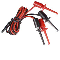
By pressing the button on each clip, you cause a spring-loaded
hook to stick out of the plastic housing. If you place the hook
around a piece of wire or a resistor, then release the button,
the clip will grab onto the wire securely with a good electrical
connection.
Verify that all is set up by sticking one end of a short jumper
wire into row "W", and sticking one end of a different wire
into row "X". Use your multimeter to measure the voltage difference
between these two wires; it should be V = 5 volts.
- Identify your resistors
-
Make sure that you have a nice selection of resistors. You should
have at least 6 each of four different types, with bands that read
- brown black brown gold
- red red brown gold
- orange orange brown gold
- grey red brown gold
Figure out the resistance of each type. If you don't know
the code, read
a quick guide to
resistor color codes.
Below is a schematic diagram showing a closeup of the
top section of the breadboard. This simple circuit
sends current from the power supply's positive terminal,
through a resistor, and back to the power supply's ground
terminal.
Can you figure out how to attach additional wires and a voltmeter
in order to measure the voltage across the resistor?
(Hint: there is no need to move any of the wires shown below).
Can you figure out how to attach additional wires in order
to measure the current running through the circuit?
(Hint: you will need to move one end of one of the wires shown below).
Warm up with a few easy circuits
- Set up a circuit with a single 100-ohm resistor.
Measure and calculate (showing all your work!)
- the drop in voltage across the resistor
- the current running through the resistor
Do your calculations match the measurements to within
ten percent?
Draw diagrams which show exactly how you connect
the multimeter to the other elements in order
to measure voltage, and in order to measure current.
- Set up a circuit with two 100-ohm resistors
connected in series.
Measure and calculate (showing all your work!)
- the drop in voltage across the first resistor
- the drop in voltage across the second resistor
- the drop in voltage across both resistors together
- Set up a circuit with two 100-ohm resistors
connected in parallel.
Measure and calculate (showing all your work!)
- the drop in voltage across the top resistor
- the drop in voltage across the bottom resistor
- the drop in voltage across both resistors together
If you have more time ....
Try more complicated circuits
- Arrange a circuit with one 100-ohm, one 220-ohm, and one 330-ohm
resistor in series.
Measure and calculate (showing all your work!)
- the drop in voltage across each resistor
- the total drop in voltage across all resistors together
- the current running through the circuit
- Arrange a circuit with two branches in parallel.
Along the top branch,
put a 100-ohm and 820-ohm resistor in series.
Along the bottom branch,
put a 220-ohm and 330-ohm resistor in series.
Measure and calculate (showing all your work!)
- the current running through the top branch
- the current running through the bottom branch
- the current running through entire circuit
Do your calculations match the measurements to within ten percent?
If you still have time ....
Now try giving your creative side
a little exercise. The problems below are puzzles;
you could use brute force to solve them,
but a little thought, some trial-and-error, and an eye for
patterns will save you a lot of time.
Using only the four types of resistor, can you create circuits
with these properties? You must draw a diagram of each circuit,
show how to calculate the total resistance, build the circuit,
and measure the actual resistance.
It's okay to be within one or two ohms in either direction.
- a circuit with resistance 220 ohms, using exactly one resistor
- a circuit with resistance 220 ohms, using exactly four resistors
- a circuit with resistance 220 ohms, using exactly five resistors
- a circuit with resistance 220 ohms, using exactly six resistors
- a circuit with resistance 62 ohms
Last modified 04/23/2004 by MWR