APOLLO Tour
This page will make you acquainted with the arrangement and progress of the APOLLO construction. For pictures taken during the initial laser installation visit, follow this link.
Start the tour by looking at a rough sketch of the layout of the components to get a feel for the names and locations of various bits and pieces.
 12/19/03
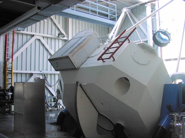
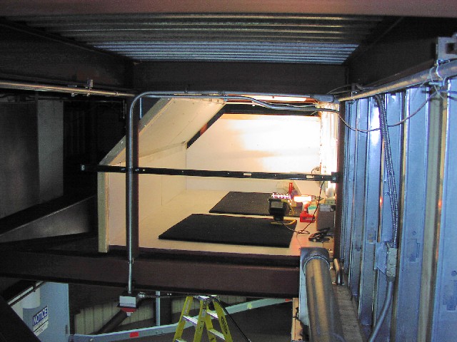
We start with a picture of the back of the telescope with the telescope enclosure doors open (thus bright). On the back of the telescope, to the left of the ladder, is the laser enclosure—sometimes referred to as "Utah" owing to its shape. In this box sits the laser, the optics/receiver, the GPS clock, and the timing electronics.
At lower-left is a box that looks like a metal phone booth. This enclosure, called the cabinet, contains all the electronics that need to be relatively close to the laser and timing system, such as the laser capacitor banks, the control computer, optics controllers, etc. This will be the control station during initial operation until remote operation capability is established.
 11/20/03
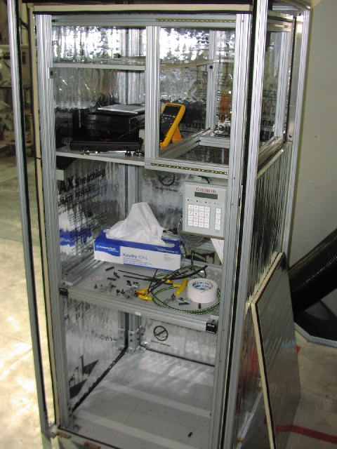
This is a peek inside the laser enclosure ("utah"). The doors swing out like refrigerator doors to allow access to the inside. The laser occupies a 2×4 foot section of the 3×4 foot optical bench. The holes in the optical bench have been taped up (right side) to prevent pesky moths from thinking this is a high-rise apartment complex. A small 100-W heater at lower right is more than enough to keep this well-insulated box warm even on the coldest of nights. The CAMAC crate containing the timing electronics will go in the upper left space, and the GPS-disciplined clock will sit at upper right above the laser bench. Three pieces of tape above the laser cover holes for the supports that will carry the weight of the clock and CAMAC units.
 11/18/04
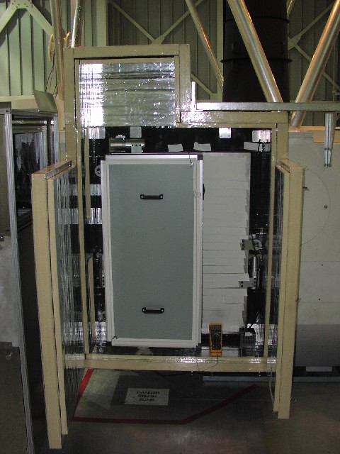
This shows the inside of the cabinet during its construction. At top left are shelves for the optics controller and CCD controller. At top right is a 19-inch rack-mount bay (sideways) where the two capacitor bank units for the laser will go. Directly below these is the laser control box. Below this is a pull-out shelf for the computer keyboard, monitor, and trackball. The computer will sit on the floor. The idea is that the entire apparatus can be operated from this position, with access to the computer, a display of the CCD, hand-paddle control of actuated optics, and laser control. Until remote operation is established, this will be the control center.
The cabinet is surrounded by 1-inch-thick polyisocyanurate insulation with taped edges and D-seal interfaces (see piece leaning against right). The air volume of the cabinet is contiguous with the intermediate-level (IL) enclosure (see picture below), though the connecting air holes and cable conduits are here taped up. The thin insulation is not enough to prevent thermal leakage, so the cabinet is surrounded by a sheet-metal plenum for routing ambient cold air around the cabinet outside, thus pulling residual heat out and through slots in the floor. A few of the slots can be seen at lower left.
 12/19/03
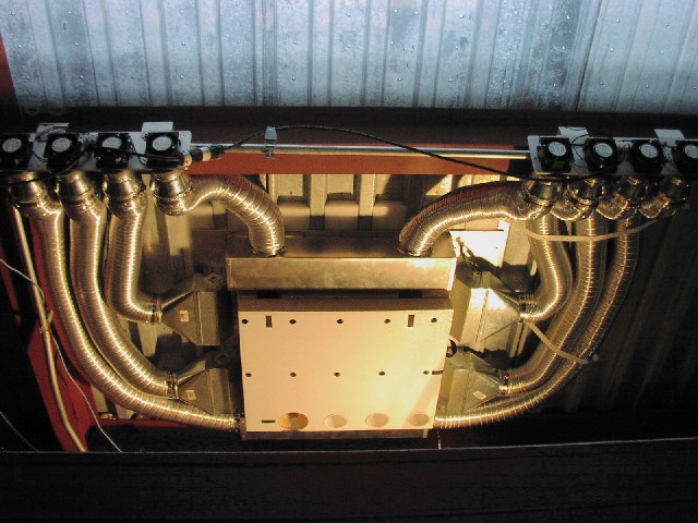
Below the cabinet (and observing floor) is the "intermediate level" (IL) of the observatory, into which we have built a platform about ten feet off the floor, and four feet below the ceiling (seen here as corrugated decking). Here we see the "octopus" arrangement of ducts that pulls air around the cabinet insulation and dumps it into the intermediate level. A rectangular patch of what will ultimately become the IL enclosure ceiling can be seen, with 1 big hole for pulling air out of the top of the cabinet enclosure (otherwise hot air would pile up here), ten small holes for air return, and three large holes for passing electrical and plumbing lines between the cabinet and IL enclosure.
 02/17/04
The outside of the IL enclosure during construction. A ladder (yellow) and door (blue) can be seen at bottom, giving a sense for the loft-like nature of the IL platform. The angled wall is necessary to allow the "octopus" ducts to pass under the I-beam. The horizontal bar on the near side of the enclosure is Unistrut, which surrounds the IL enclosure and gives it strength.
 05/10/04
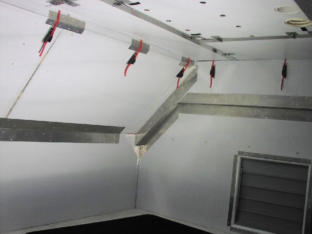
The finished IL enclosure interior. The ceiling panel interface to the cabinet can be seen at top right. The removable ceiling panels all latch into place and are held down on the edges with bungee cord (red). The louvre at right (actually a double-louvre box) admits air into an exhaust fan, and a similar set of louvres on the other side of the enclosure admits ambient air in. When the system is running, we will be dumping several kilowatts into the intermediate level. From here, air is rapidly moved well away from the telescope by the observatory's air handling system.
 05/10/04
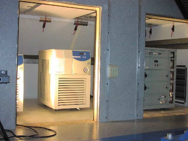
Looking into the double-doors of the IL enclosure, with the primary occupants rolled into place. Through door number one are two chillers; the left (smaller) chiller takes heat out of the laser enclosure on the telescope. The larger chiller removes heat from the laser flashlamps/rods through an interface controlled by the laser electronics rack (lowest unit in the rack). Through door number two is the laser electronics rack, holding everything but the two capacitor units that occupy the top portion of the cabinet enclosure. From top to bottom are the control unit, the RF generator for acousto-optic modulation, two power supply units, and the "cooling group," which controls the thermal state of the laser rods.