 Copyright © Michael Richmond.
This work is licensed under a Creative Commons License.
Copyright © Michael Richmond.
This work is licensed under a Creative Commons License.
Enough theory -- it's time to put physics to the test. Your job today is to set up a system which oscillates, predict its resonant frequency, and then check to see if you were correct.
Calculations of uncertainty will be given a high weight in today's experiment.
You will have to figure out what to do for most of today's activity. Feel free to ask for help.
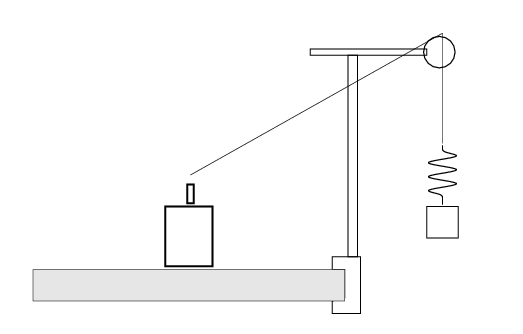
Set the amplitude of the driver to the 9 o'clock position. Starting at about 10 Hertz, drive your system and measure its amplitude of oscillation. Watch for at least 5 or 6 cycles at each setting, and choose the largest amplitude you see.
Make a table of measurements from 10 Hertz down to 1 Hz. Adjust the steps in frequency to "zoom in" on interesting behavior.
If you have time, for extra credit .....
A resonant system will often show behavior like that in the graph below: the amplitude of oscillations reaches a peak at some central frequency ω, with some width Δω around that peak.
The "quality factor", Q, of a system, is a measure of how narrow the peak is. The narrower the peak, the higher the Q factor.
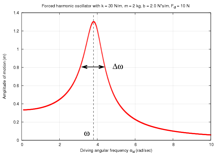
                      ω
          Q   =     -----
                     Δω
Systems with high Q values will tend to oscillate for longer duration before the damping causes them to decrease and stop moving. In fact, to a rough approximation, it is said that
       Q    is approx    number of cycles required for the system's
                         energy to fall to

                                1  /  e2π

                         of the original energy
Copyright © Michael Richmond.
This work is licensed under a Creative Commons License.