 Copyright © Michael Richmond.
This work is licensed under a Creative Commons License.
Copyright © Michael Richmond.
This work is licensed under a Creative Commons License.
The heart of the problem is that there's a big, bright star very close to our real target, the planet. If even a tiny fraction of the star's light is scattered out into its wings, that might increase the noise so much that the planet drowns in it.
Some of the scattering takes place inside our optics and detector. But if we can prevent (most) of the light from that host star from REACHING the optics, we can stop that scattering before it even begins. That's the idea behind the coronograph.
If you're lucky, you might find a natural object of just the right size, in just the right place, at just the right time:
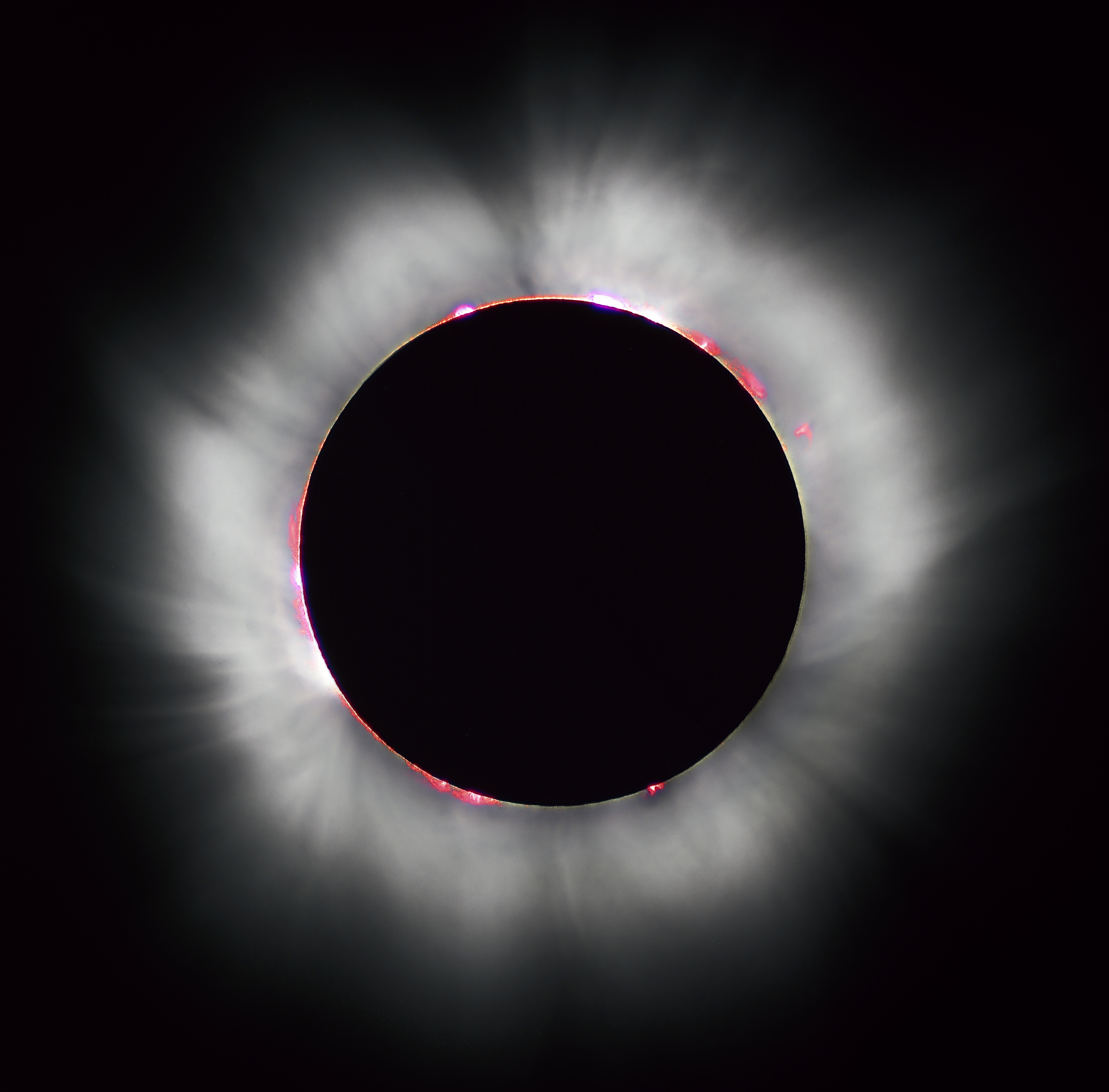
Image of solar eclipse taken from
Wikipedia , thanks to
Luc Viatour
If not, you can place a big object very far in front of your telescope.
But most coronographs use optics to bring light from the star to a focus, where it can be blocked internally. This isn't as good as an external device, but it's a heck of a lot more practical.
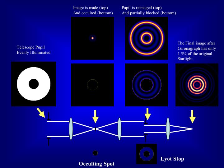
Diagram courtesy of
The Lyot Project
Images taken with coronographs will show a tell-tale dark circle near the center, since (in theory) all the light from the central source has been blocked.
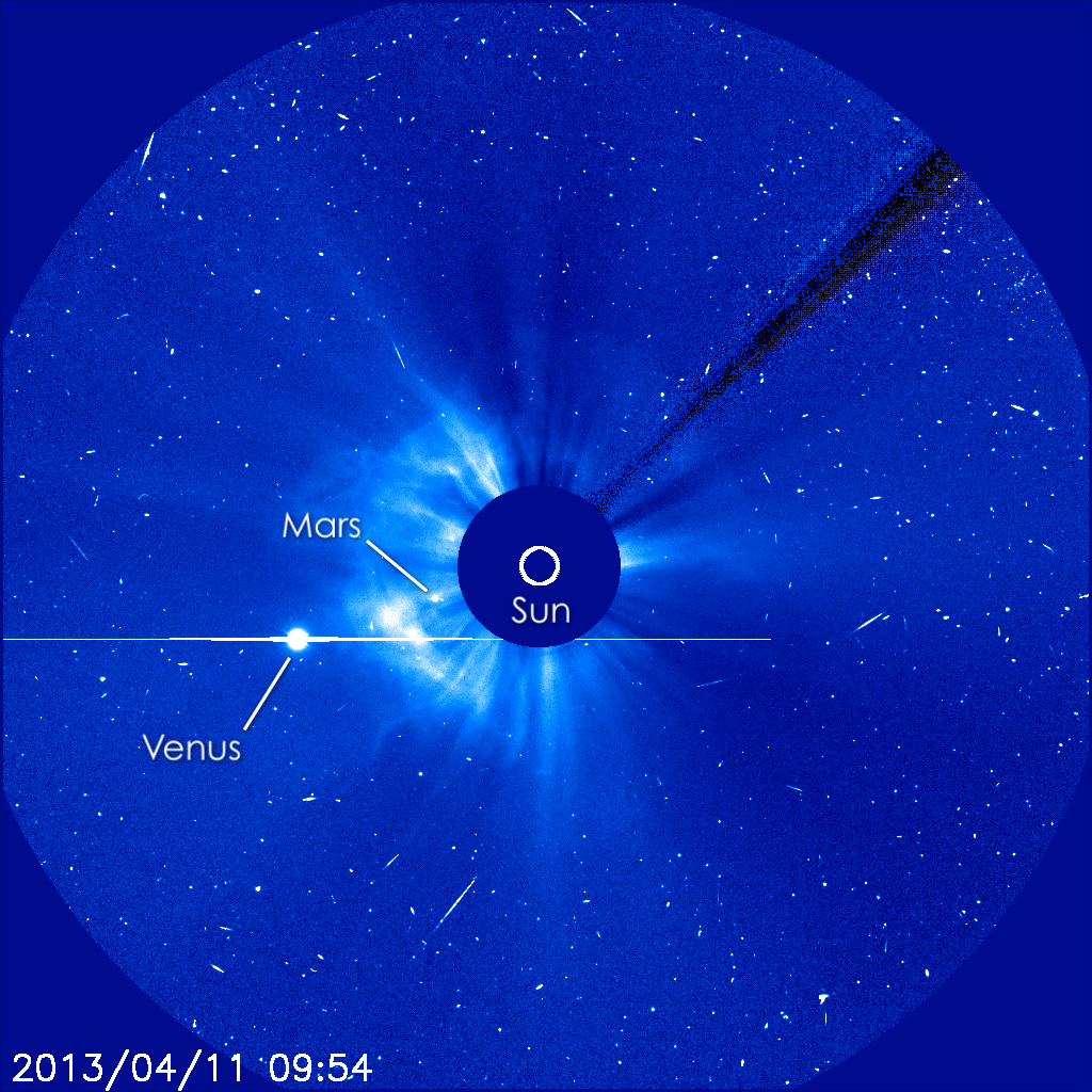
Image taken by
the SOHO spacecraft
Okay, let's look at one device specifically designed to look for exoplanets. The Lyot Project coronograph was installed on the 3.63-m AEOS telescope in Hawaii, where it took images of the young star AB Aur. You can see light from a disk surrounding this star.
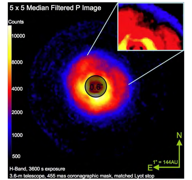
Figure 2 taken from
Oppenheimer et al., ApJ 679, 1574 (2008)
How well does this instrument remove the light of the bright star? Well, take a look at the radial profile:
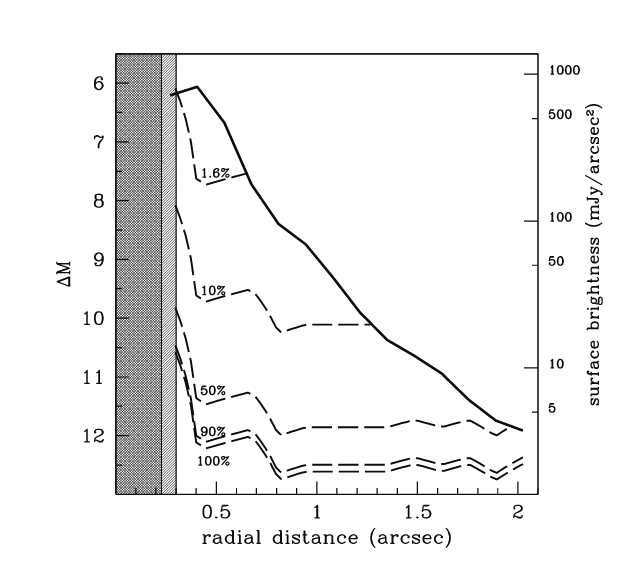
Figure 3 taken from
Oppenheimer et al., ApJ 679, 1574 (2008)
  Q:  At an angular distance of 1 arcsecond, this device
      can detect an object how many magnitudes fainter
      than the central star?


  Q:  How does that compare to the "delta-mag" for
      a Jupiter-like planet orbiting a Sun-like star
      at 5.2 AU?


  Q:  How does that compare to the "delta-mag" for
      a hot Jupiter, orbiting a Sun-like star at 0.04 AU?
By themselves, coronographs can't solve all our problems -- but they can help. Several of the current planet-finding teams incorporate a coronograph into the design of their system.
Another approach is to "sharpen" the PSF, so that a smaller fraction of light from the host star will extend out to the surrounding regions. Astronomers using ground-based telescopes have suffered for centuries: their views were always limited by distortion created by the Earth's atmosphere.
In theory, the diffraction limit for a telescope is set by its diameter:
      Express your answers in arcseconds.


  Q:  What is the diffraction limit for a D = 10 m telescope
      in the optical V-band -- at 5000 Angstroms?


  Q:  What is the diffraction limit for a D = 10 m telescope
      in the near-IR K-band -- at 22000 Angstroms = 2.2 microns?
But in practice, the limit has always been set by the Earth's atmosphere at around 1.0 arcsecond; maybe 0.6 arcseconds at a very good site, under good conditions.
In the past three or four decades, the combination of sensitive solid-state detectors and (especially) very fast computers has permitted astronomers to design systems which will
One version of this idea involves actuators in the support system for the primary mirror:
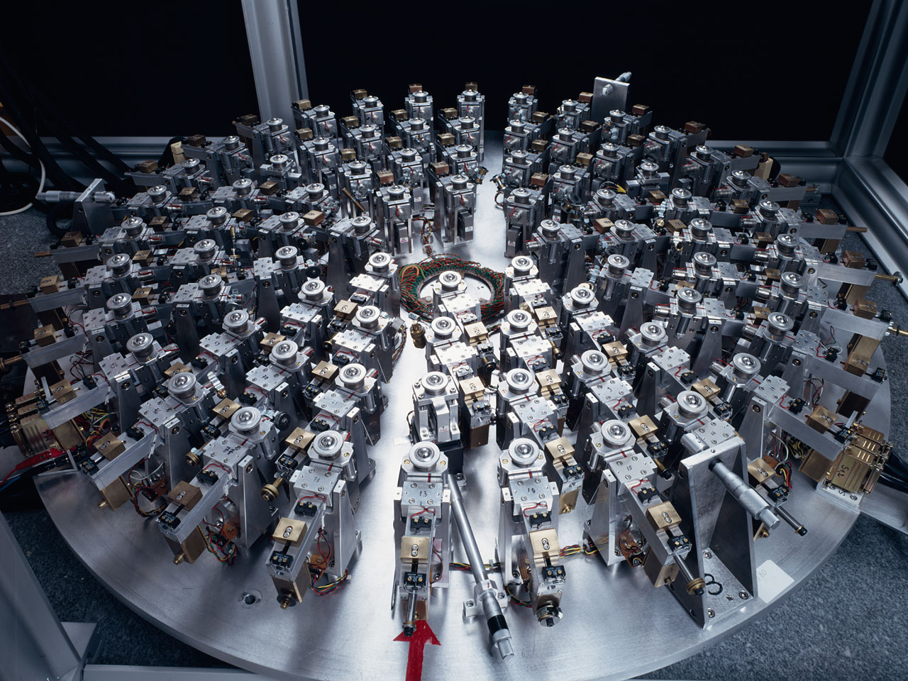
Image of
a 1-m test system developed by the ESO
A small portion of the incoming light is diverted to a "distortion camera", which measures the shape of the wavefront. A fast response system then adjusts the shape of the mirror in order to cancel out some of the deviations of that shape from the desired form.
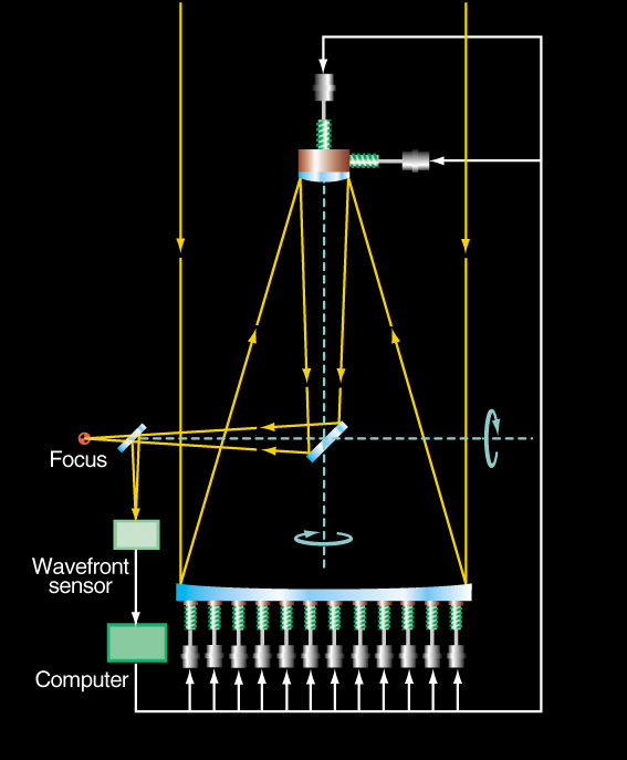
Active Optics schematic
courtesy of the ESO
Unfortunately, it's not possible to move sections of a big, heavy slab of glass quickly enough to keep up with the motions of the air, so this sort of system can only remove some slow-changing components of the distortion.
In order to correct for the quickly-changing variations, one needs to adjust a small, lightweight optical surface -- often a so-called "rubber mirror" does this job.
Figure 6 from
Rausch et al., Optics Express 23, 19469 (2015)
How do we know exactly how to correct for the atmospheric distortions? Well, if there happens to be a single, isolated, bright star near our target, we KNOW what it should look like: a point source. So, if we monitor that "reference star" with our fast camera, and adjust the rubber mirror so that the reference star changes from a fuzzy blob into a sharp point, then our target should ALSO be sharpened.
This is a simplification, of course. It also ignores the question of "how nearby must the reference star be?"
In the example below, there's a big, bright single star which we can use as a reference. When we adjust the optics so that it turns into a sharp point source, the fainter source nearby turns into TWO point sources.
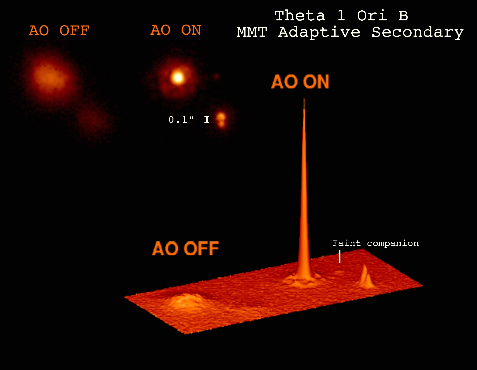
Figure from
Steward Observatory
   Q:   But what if there aren't any bright, isolated, single
        stars near our target?

        How can we make the proper corrections in this case?
If there aren't any point sources nearby, we'll just have to make some point sources ourselves!
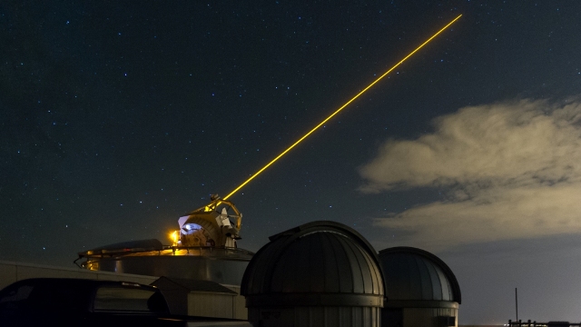
Image courtest of
The US Air Force and Boeing
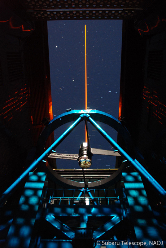
Image courtesy of
Dr. Sebastian Egner and Subaru/NAOJ
It's a difficult job, but the results can be impressive, as this Gemini Planet Imager picture of the brown dwarf (not exoplanet) companion to HD 1160 demonstrates.
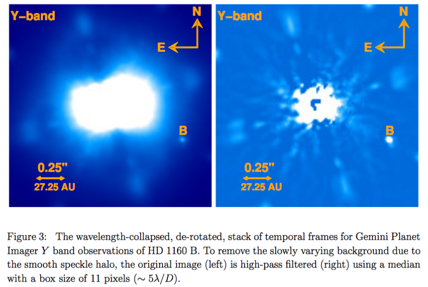
Figure 3 taken from
Garcia et al., arXiv 1610.05786 (2016)
Another recent example of the performance of the Gemini Planet Imager working at H-band is shown below.
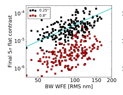
Figure 7 taken from
Bailey et al., arXiv 1609.08689 (2016)
  Q:  In the graph above, what is the "5-sigma" contrast ratio at
      an angular distance of 0.25 arcseconds achieved
      by the Gemini Planet Imager?


      What is the corresponding delta-mag value between
      star and a detectable nearby planet?
You may have noticed that the examples of adaptive optics shown here, and most observations made in real life, are in the near-infrared region of the spectrum: between 1 and 3 microns. But we know that diffraction would produce a sharper image at shorter, visible wavelengths.
So, why do astronomers use their adaptive-optics cameras in the near-infrared?
The answer turns out to lie in the atmosphere. The shorter the wavelength, the more violent the distortions by the air, AND the more quickly those distortions change as wind carries the air past the telescope. It just happens to be possible for current instruments to keep up with the changing atmosphere if they work in the near-infrared -- so that's where astronomers look.
For an example of the very small size of the isoplanatic patch, even at near-infrared wavelengths, see the discussion at
I recommend scrolling down to the very end of the page and examining the sample images carefully.
PZ Tel has a companion which is a bit too massive to be an exoplanet (perhaps 35 Jupiter masses), but it allows us to compare views through several different instruments.
PZ Tel observed with Nasmyth Adaptive Optics System Near-Infrared Imager and Spectrograph (NACO) on the VLT in 2012:
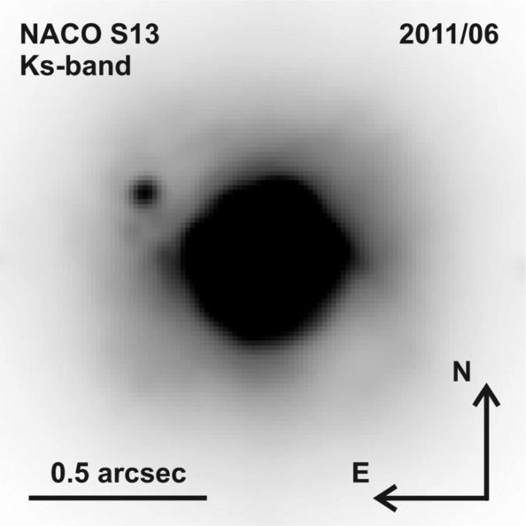
Figure 1 from
Mugrauer et al., MNRAS 424, 1714 (2012)
PZ Tel observed with Near Infrared Coronographic Imager (NICI) on Gemini-South in 2010:
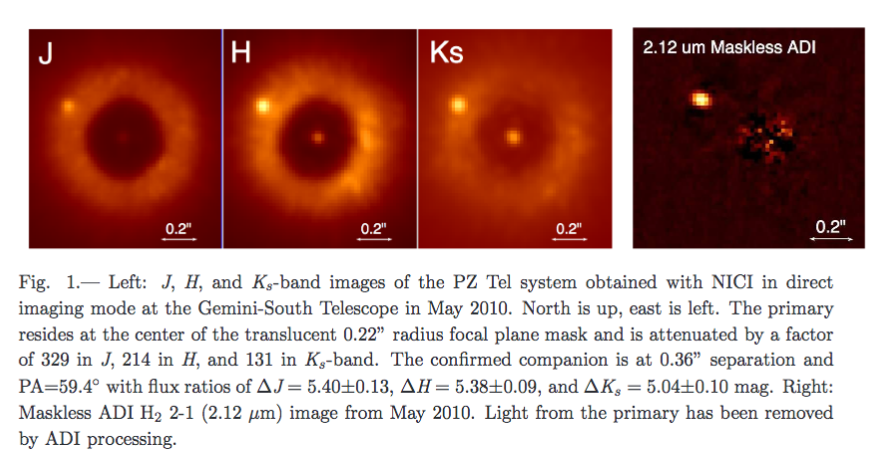
Figure 1 from
Biller et al., ApJ 720, 82 (2010)
PZ Tel observed with IRDIS (part of Gemini Planet Imager) on Gemini in 2014.
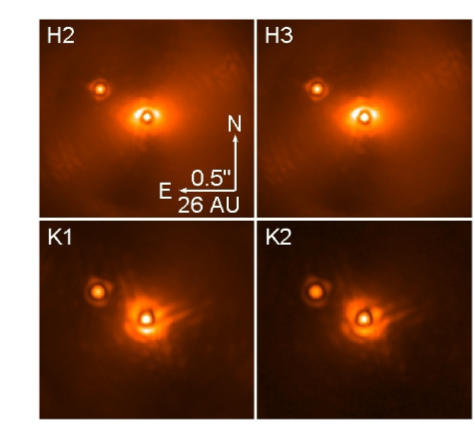
Figure 1 from
Maire et al., A&A 587, 56 (2016)
  Q:  What is the magnitude difference between PZ Tel
         and its companion?


      How does that compare to the magntiude difference
         between a sun-like star and a hot Jupiter?
HD 95086 b with the Gemini Planet Imager
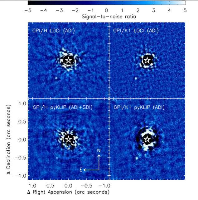
Figure 1 taken from
DeRosa et al., ApJ 824, 121 (2016)
In this case, the magnitude difference between the star and planet is pretty big: 13.7 mag in H-band (1.6 microns), 12.2 mag in K-band (2.2 microns), 9.5 mag in L-band (3.5 microns).
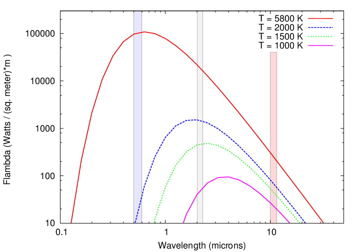
Note that the difference in magnitude shrinks at longer wavelengths. Why? Because in this case, the very young planet (estimated age 17 Myr) is still so hot (800 - 1300 Kelvin) that it is radiating strongly on its own. Remember this?
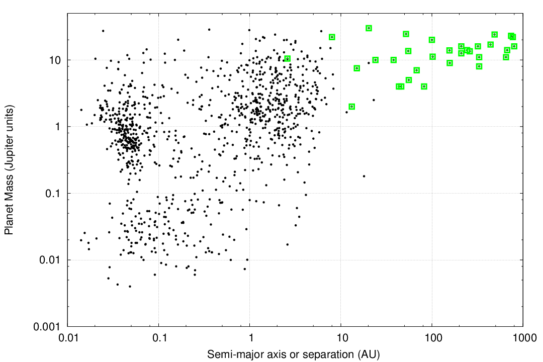
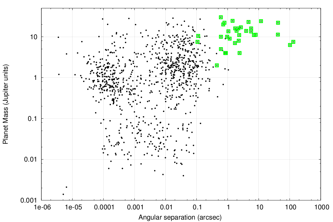
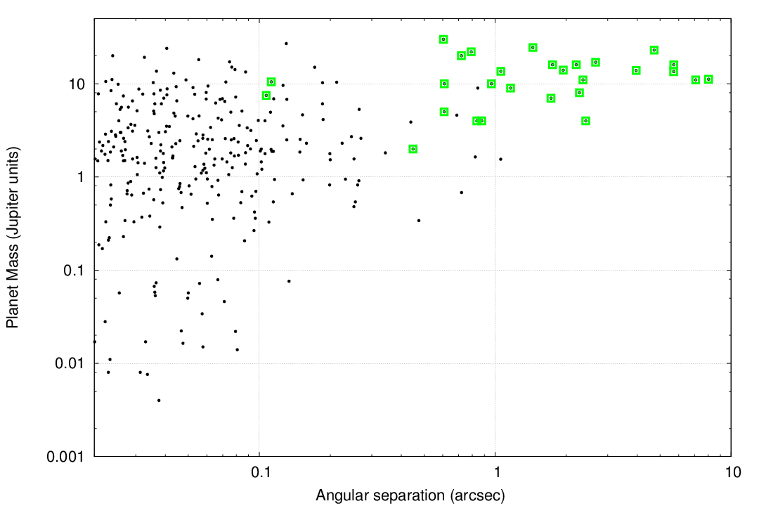
Galicher et al. (2016) present the results of a large, international imaging survey for giant planets around 292 nearby stars. Some of their conclusions reveal the biases inherent in this approach.
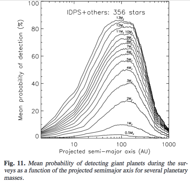
Figure 11 from
Galicher et al., A&A 594, 63 (2016)
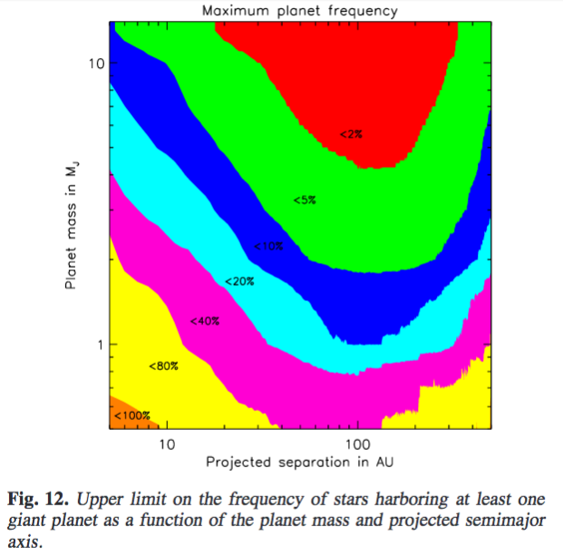
Figure 12 from
Galicher et al., A&A 594, 63 (2016)
Copyright © Michael Richmond.
This work is licensed under a Creative Commons License.