 Copyright © Michael Richmond.
This work is licensed under a Creative Commons License.
Copyright © Michael Richmond.
This work is licensed under a Creative Commons License.
The earliest and simplest telescopes are refractors. They consist of a long, narrow tube with a lens at the front end. Light which passes through the lens is bent, so that initially parallel rays meet near the bottom of the tube.
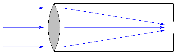
Refractors are easy to make and, when small, relatively inexpensive. Large telescopes of this sort become unwieldy. The largest refractor ever put to practical use is the Yerkes 40-inch instrument; its aperture (front lens) is 40 inches in diameter. The tube is a bit longer ...
There are several drawbacks to this design:
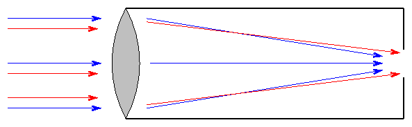
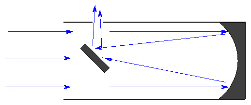
Isaac Newton realized that mirrors would solve the second problem: they can bring light of ALL wavelengths to a common focus. He designed a telescope which used mirrors to reflect light; hence, this type is called a reflector.
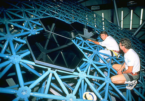
The mirror in a reflector can be supported not only around the edges, but also all over the back surface. That means that very large mirrors can be placed into telescopes. The Subaru Telescope has a primary mirror over 8 meters in diameter.
Why build large telescopes? It's not to magnify objects -- the Earth's atmosphere blurs everything to a minimum resolution of about 1 arcsecond. In order to see really fine detail in the optical, you have to move your telescope above the atmosphere:
The real reason astronomers want big telescopes is to detect fainter and fainter objects. The faintest object visible in a telescope depends on the amount of light the telescope can gather ... which in turn depends on its collecting area:
                              2
        area  =  pi * (radius)
Note that the collecting area increases as the square
of the radius (or diameter).
   Q:   The pupil in your eye has a diameter of about 5 mm.
        The little telescope at the front of the class has a
        diameter of about 4.25 inches.

        Q1:   What is the ratio of collecting area of the telescope
              to collecting area of the eye?

        Q2:   How many times fainter are the faintest objects you can see
              in the telescope, compared to the faintest object you can
              see with your naked eye?

        Q3:   If the unaided eye can see stars of mag m = 5,
              what is the magnitude of the faintest stars visible
              through this telescope?
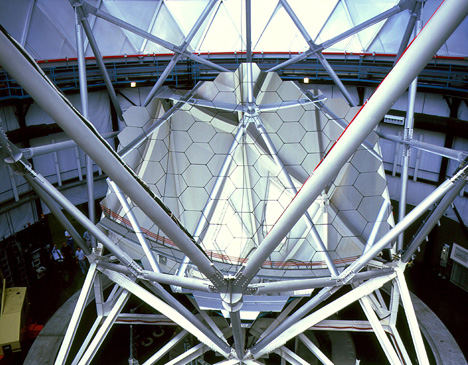
At some point, however, even though you can support your big mirror across its entire back surface, the mirror becomes so big and so heavy that it starts to sag. Even worse, as you move your telescope to point to different regions of the sky, your mirror will sag in different ways. The mirror will no longer bring all the light rays to a single focus. Our current technology has just about reached that point with mirrors of diameter 8 meters.
What can you do if you want to see even fainter objects?
Answer: use an array of smaller mirrors.
The Keck Telescopes:
The Hobby-Ebberly Telescope:
The James Webb Space Telescope:
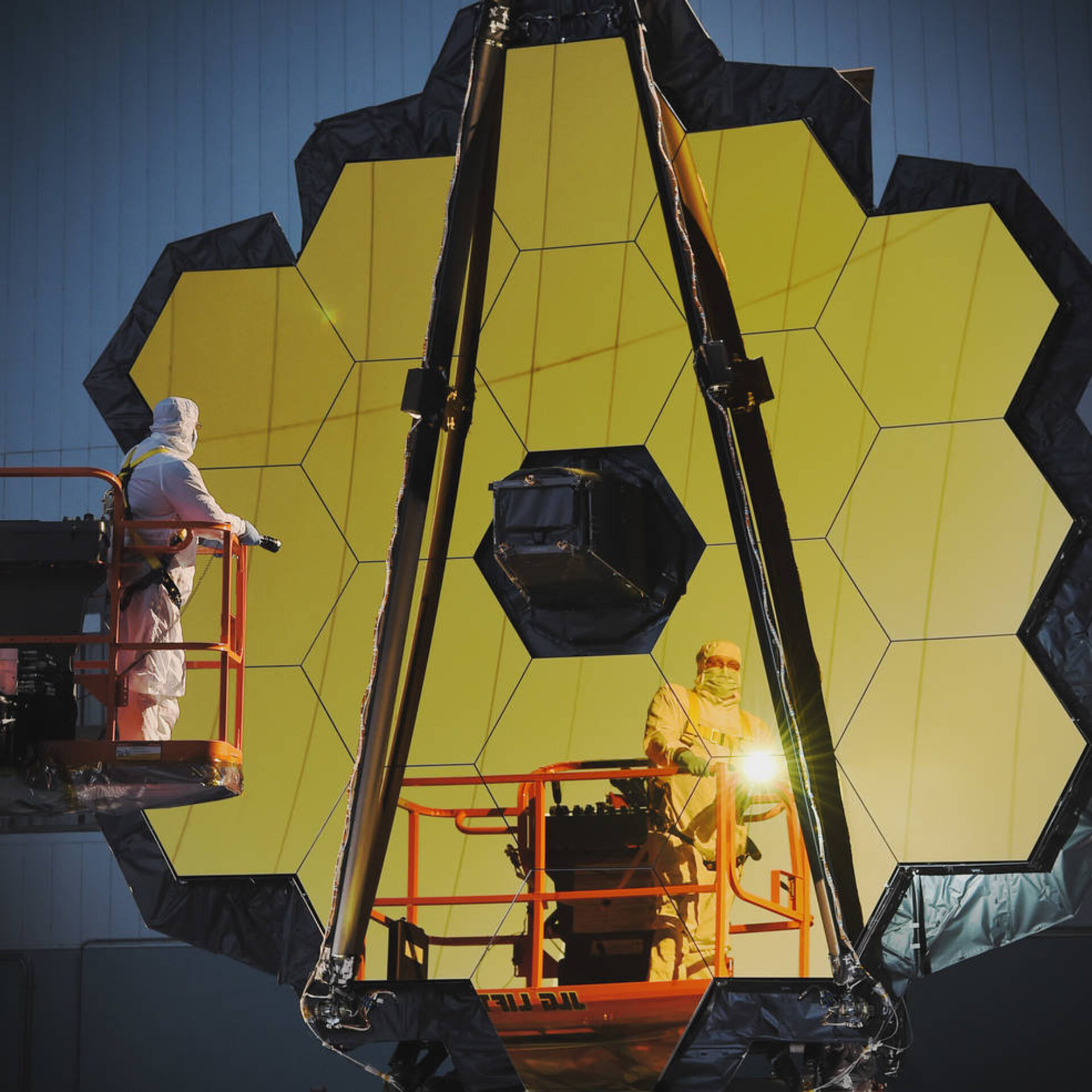
Image courtesy of
European Space Agency
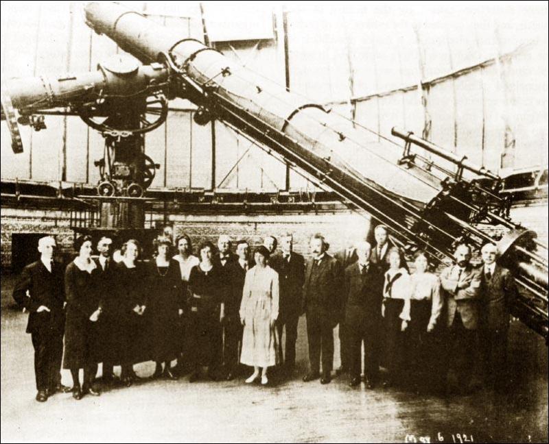
In the late 1800s, the refractor was King: the largest telescopes in the world were the 36-inch at Lick Observatory and the 40-inch at Yerkes.
But around the turn of the century, astronomers decided that they needed as much light-gathering power as possible in order to measure spectra and detect faint stars and galaxies on photographic plates. Reflectors could be made larger than refractors, so the tide turned, and mirrors with larger and larger diameters took over. George Ellery Hale was the driving force behind the construction of a series of very influential instruments:
For most of the twentieth century, refractors fell out of the mainstream of professional astronomical research.
But in the past 20 years, they made a strong resurgence, as a result of three factors:
One of the cheapest and most efficient ways to find (and characterize) exoplanets is via the transit method. All it takes is the ability to measure the light from a star to a tenth of a percent or so (in other words, to the millimag level). But since there are so many stars in the sky, in order to find the rare transit events, one must measure thousands or tens of thousands of stars at a time. Which brings us to ...
| Mag | Approx. Number of stars |
| 5 | 2000 |
| 6 | 6000 |
| 7 | 18,000 |
| 8 | 52,000 |
| 9 | 190,000 |
| 10 | 450,000 |
| 11 | 1,300,000 |
In order to check them all for exoplanets -- or for other interesting properties -- it makes sense to use an instrument which has a wide field of view, so that you can measure hundreds or thousands of stars in a single image.
The same is true if one is searching for rare transient events, such as GRBs, SNe, or the optical counterparts to gravitational wave sources. Starting in the late 1980s, astronomers started to combine wide-field telescopes, electronic cameras, and computer-controlled motors in order to carry out surveys of large sections of the sky in an automated manner. I enjoyed dabbling in the early days of automating telescopes myself ...
A connection between football and astronomy?

Sports Illustrated cover for Jan 24, 2011
Yes! Photographers who cover sports need lenses with two key properties:
Well, these are exactly the same major concerns of astronomers. But since there are many more professional sports photographers than astronomers, and since their newspapers and magazines and websites will pay them well to get good pictures, some of the major lens makers have created lenses which meet these needs and are not too expensive. This article might give you some idea for the lenses commericially available.
Q: What are the typical prices for these lenses?
Let's go through one example to see how this works. We begin with a lens, of diameter D and focal length L.
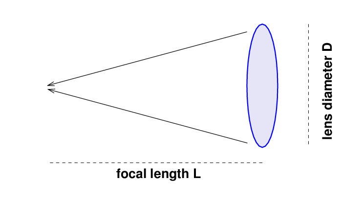
The focal ratio of the lens is
On the other end of the camera is a detector with pixels.
![]()
The relationship between a pixel's physical size p and its angular size α on the image plane is simply
Now, some typical numbers for astronomical instruments of interest, as you will see eventually, are
That might sound like a small telescope, but it's a pretty darn big lens.
One can use this information to compute the angle subtended by pixels in a telescope, and the solid angle covered by each pixel.
   Lens Diam D   focal ratio   focal length   pix ang size   pix ang area
     (mm)           f              L (mm)        (arcsec)     (sq. arcsec)
 ----------------------------------------------------------------------------

    100            2.5

    100            5

    100           10

    100           15

 ----------------------------------------------------------------------------
Here's the filled-in version.
   Lens Diam D   focal ratio   focal length   pix ang size   pix ang area
     (mm)           f              L (mm)        (arcsec)     (sq. arcsec)
 ----------------------------------------------------------------------------

    100            2.5            250             8.25           68.07

    100            5              500             4.12           17.02

    100           10             1000             2.06            4.25

    100           15             1500             1.38            1.89

 ----------------------------------------------------------------------------
Let's pick as a target the planet Jupiter!
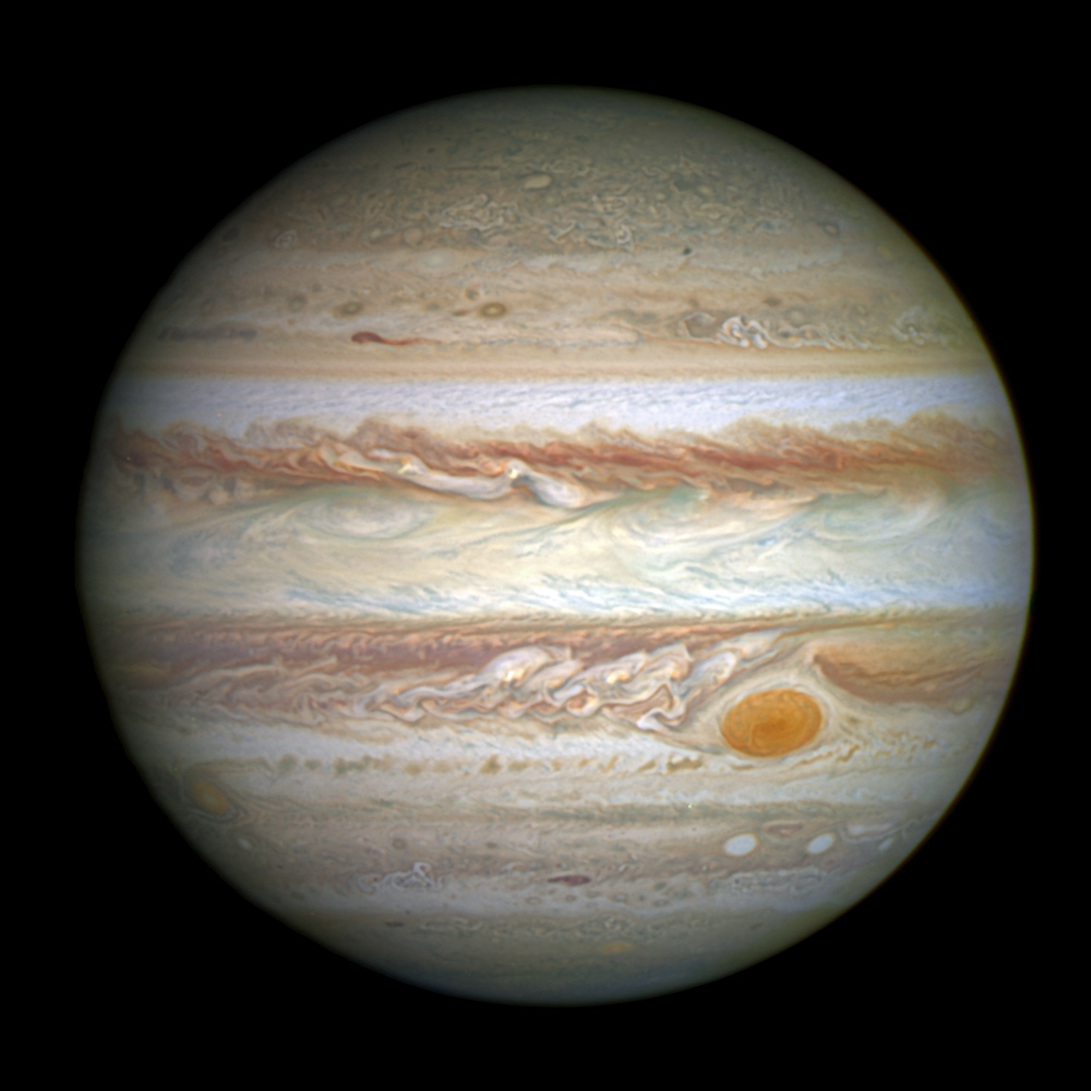
Image of Jupiter courtesy of
NASA and hubblesite.org
Some representative numbers for Jupiter (which of course changes in size and brightness as it and the Earth move around the Solar System) are
We'll need to use these basic facts to figure out a couple of more pertinent parameters: how many photons we can expect to gather from Jupiter, and how those photons will be spread out over our CCD's pixels.
For the first, we'll use the nice and simple approximation that
     A star of magnitude V = 0 sends through the V-band filter

                   photons
            106  --------------
                 sq.cm. * sec
   Q:  How many photons per second will enter our camera?


   Q:  If we insert a narrow-band filter which transmits only
          0.1% of the incident light, how many photons per second
          will reach our detector?
Okay, now we need to figure out the area on our CCD over which this light will be spread.
  Q:  What is the angular area of Jupiter's disk
          (express your answer in square arcseconds)?
Right. With this information, we can continue our table of values to include the number of photons per second striking every pixel:
  Lens Diam D   focal ratio   pix ang area   photons per sec
    (mm)           f          (sq. arcsec)      per pixel
----------------------------------------------------------------------------

   100            2.5           68.1             26,847

   100            5             17.0              6,713

   100           10              4.25             1,676

   100           15              1.89               745

----------------------------------------------------------------------------
Do you see the tradeoff? A larger focal ratio, and longer focal length, creates much smaller pixels ... but that means that the light from any object in the sky will be spread out over many more pixels. If we are fighting against sources of noise -- such as background light or readout noise or dark current -- which affect each pixel independently, then we will lose the signal-to-noise battle as the light of our target is spread out over many pixels.
In other words, a short focal ratio means big pixels, and big pixels mean a higher signal-to-noise ratio in short exposures.
  Q:  What happens if we make the focal ratio _too_ small,
           and the pixels get _too_ big?
Yes, if the pixels are so large that they cause neighboring stars to blend together, we won't be able to measure the light of each star properly. That brings up another question: just what is the typical distance between stars? It would be convenient to express this in arcseconds, of course.
Let's choose stars of magnitude 10. There are very roughly 500,000 (half a million) such stars, and let's assume that they are spaced evenly all over the sky. In real life, of course, there are more in certain directions.
  Q:  How many square degrees does it take to cover
          the entire sky?


  Q:  How many stars of mag 10 can we expect to find
          in each square degree?


  Q:  What is the typical distance between mag 10 stars?
          (in degrees, and in arcsec)
Right. So, armed with this knowledge, we know that wide-field surveys which target hundreds or thousands of stars at a time will want to use a lens with LARGE diameter (and hence large focal length), but SMALL focal ratio. The typical description of a lens in photographic catalogs looks like
           200 mm              f/4

          focal length       focal ratio
Can you find prices for lenses which have focal lengths between 150 mm and 300 mm, and focal ratios between f/1.2 and f/6?
In particular, you might check out the Canon 200mm f/1.8, which has been adopted by several astronomical projects.
You might be wondering why I'm spending so much time to talk about surveys of "boring old stars" with magnitudes between 8 and 12. Well, one reason is that I've spent quite a bit of time working on a couple of surveys of this type, so this is stuff I actually understand pretty well.
Here's a picture of one of the Mark III triplets, showing the three telescopes (each a camera lens and CCD) which point at the celestial equator.
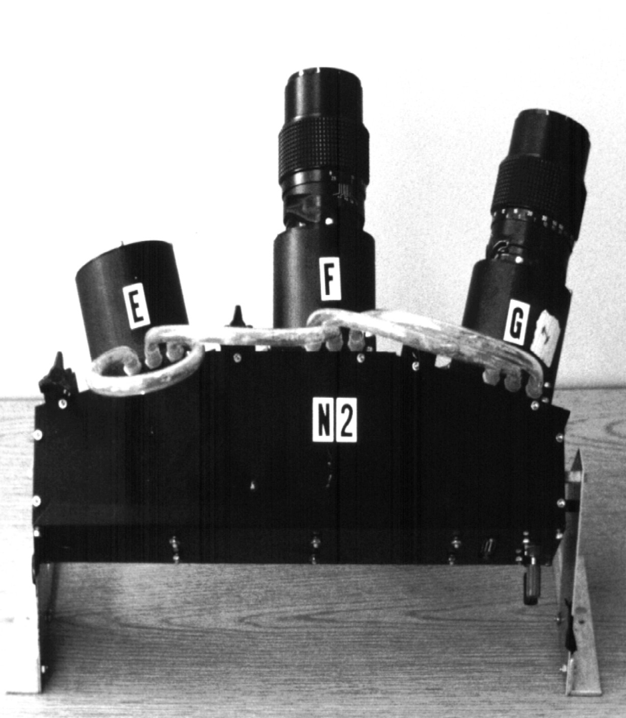
Figure 1 taken from
Richmond et al., PASP 112, 397 (2000)
The telescopes don't move; instead, they operate in "drift-scan" mode, reading out the CCD at exactly the same rate that stars drift across the field of view. The optics in this system are 135mm f/2.8 lenses.
Q: Why were these lenses chosen for TASS Mark III?
The future looks bright for refractors in astronomy, as many people remain fascinated by exoplanets and relatively bright transient sources. If you go to this webpage from my 'Exoplanets' course, you can see some examples:
  Q:  Evryscope is built around Rokinon 85mm f/1.4 camera lenses.
         How much does each of these lenses cost?


  Q:  How many lenses does the Evryscope have?


  Q:  What is the total cost of all the optics?
Evryscope has published a small number of papers in recent years, including
The much larger TESS project has produced a slew of results, largely focusing on exoplanets:
Copyright © Michael Richmond.
This work is licensed under a Creative Commons License.