 Copyright © Michael Richmond.
This work is licensed under a Creative Commons License.
Copyright © Michael Richmond.
This work is licensed under a Creative Commons License.
As we continue to move to longer and longer wavelengths, we enter a region which has several names. It is sometimes called the "far-infrared", and other times the "sub-millimeter." In a way, this region marks a dividing line between "photons, described by wavelength" to "waves, described by frequency."
Let's work out some of the numbers. Please fill in the frequencies corresponding to these wavelengths.
       wavelength                         frequency
---------------------------------------------------------------

     1 micron

    10 microns

   100 microns

  1000 microns   =  1 mm

 10000 microns     10 mm =   1 cm

                  100 mm    10 cm

                 1000 mm   100 cm = 1 m

---------------------------------------------------------------
As we went from the optical to the infrared, the Earth's atmosphere started to block the radiation from celestial sources, so that we needed to go to space to see the mid-IR. But as we continue to look at longer and longer wavelengths, the atmosphere starts to become transparent again.
![]()
One of the biggest differences between traditional optical detectors (CCD and CMOS) and the devices made for the far-IR and millimeter regime is the ratio between the size of the detector, and the wavelength of the radiation.
In the optical, for example,
  Q:  A typical CCD pixel is 10 microns on a side.
      A typical photon has a wavelength of 0.5 microns.

      What is the ratio of

               (pixel size) / (wavelength)
In simple terms, it's not difficult to cause a small photon to interact with a big chunk of silicon.
But what about the far-IR? The wavelengths are much bigger --- 1000 times bigger --- but the detectors are not correspondingly 1000 times larger. In fact, one of the devices we'll discuss in a moment has "pixels" which are roughly 1.5 mm in diameter.
  Q:  A "pixel" in Herschel's SPIRE is about 1.5 mm on a side.
      A typical photon has a wavelength of 500 microns.

      What is the ratio of

               (pixel size) / (wavelength)
Detecting photons which are comparable in size to one's instrument presents some challenges.
Another big difference is the energy contained within each photon. At far-IR wavelengths, an individual photon doesn't have enough energy to promote an electron to the conduction band of most materials; and even if one designs a material with the right gap, thermal noise will promote many false electrons for each photo-generated one.
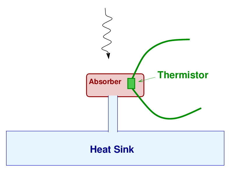
So, instruments in the far-IR use a different principle to note the presence of incoming photons from space. Instead of knocking free electrons, the photons will modify the bulk properties of a tiny sample of material. For example, the photons might heat the sample slightly, causing its resistance to the flow of current to change slightly. These devices are called bolometers.
Here's a simple schematic showing the basic idea. A small "absorber" is connected via a thin strip of thermal conductor to the "heat sink", which stays at a constant (very low) temperature. Embedded inside the absorber is a tiny thermistor, the electrical resistance of which changes with its temperature. When a photon strikes the absorber, it raises its temperature a bit, modifying the properties of the current running through the thermistor. After a short time, the extra thermal energy of the absorber is conducted away into the heat sink, the absorber returns to its usual temperature, and the electrical circuit returns to its usual voltage (or current).
These bolometers can be efficient, detecting over half of the incoming photons which strike them. They are read out very rapidly, at roughly 100 times per second.
Let's consider the instrument called Spectral and Photometric Imaging Receiver (SPIRE) on the Herschel satellite. A picture of bolometer from a prototype of the instrument is shown below. You can see the thermistor sitting in the center of a "spider-web" of mesh.
Taken from Figure 1 of
Bock et al., 2002 Monterey meeting
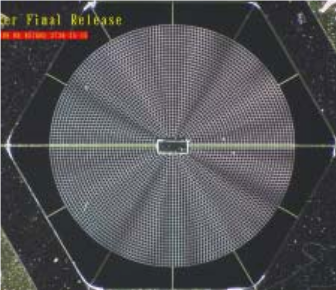
Here is one of the actual elements of SPIRE itself; this time, the thermistor is mounted off-center in the mesh.
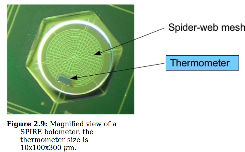
Figure 2.9 of the
Herschel SPIRE Handbook
Now, the detectors themselves are tiny: each just a few hundred microns across. But if you look at the SPIRE focal plane, you will see three arrays (one for each band) which span a very large area, about 45 mm wide. In the case of the 500 micron array, each "pixel" in the focal plane covers a region about 5 mm wide. In other words, in these pictures, the circles are much larger than the pixels.

A portion of Figure 3 taken from
Griffin et al., arXiv 1005.5123 (2010)
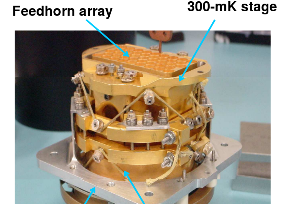
What's going on here? The circles on the focal plane represent the openings of a set of feedhorns, shaped like funnels, which "funnel" the light down into the actual detector.
A portion of Figure 3 taken from
Griffin et al., arXiv 1005.5123 (2010)
  Q:  Why use these horns to send the light down onto the teeny-tiny
         detectors?  Why not just make the detectors larger?
These bolometers must be cooled to VERY low temperatures in order to detect faint celestial sources. The detectors in SPIRE are cooled to 0.3 Kelvin! That requires some serious cryogenics.
Let's look briefly at the properties of two far-IR instruments: one in space (Herschel), and one on the ground (JCMT).
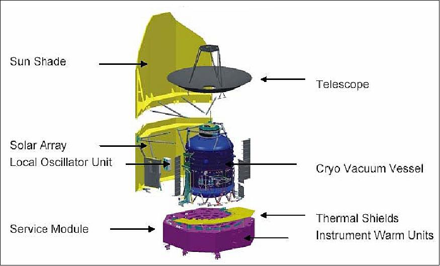
Image taken from Chapter 2 of Herschel Observers' Manual
Herschel contained three main instruments, but we'll focus here on the one called SPIRE, a camera and imaging spectrometer covering 250, 350 and 500 microns.
Herschel started science operations in 2009, and ran out of cryogenic coolants in April, 2013. During those four years, it observed a wealth of sources.
          Q:  Use the  SkyView Query Form  to request an image
                  of M74 taken with the "DSS2 Red" survey,
                  AND the "WISE 22 micron" survey.
                  Use 600 pixels and a 0.20 degree field.
          Q:  Compare those results to images of M74 taken with
                   Spitzer and Herschel  at much longer wavelengths.
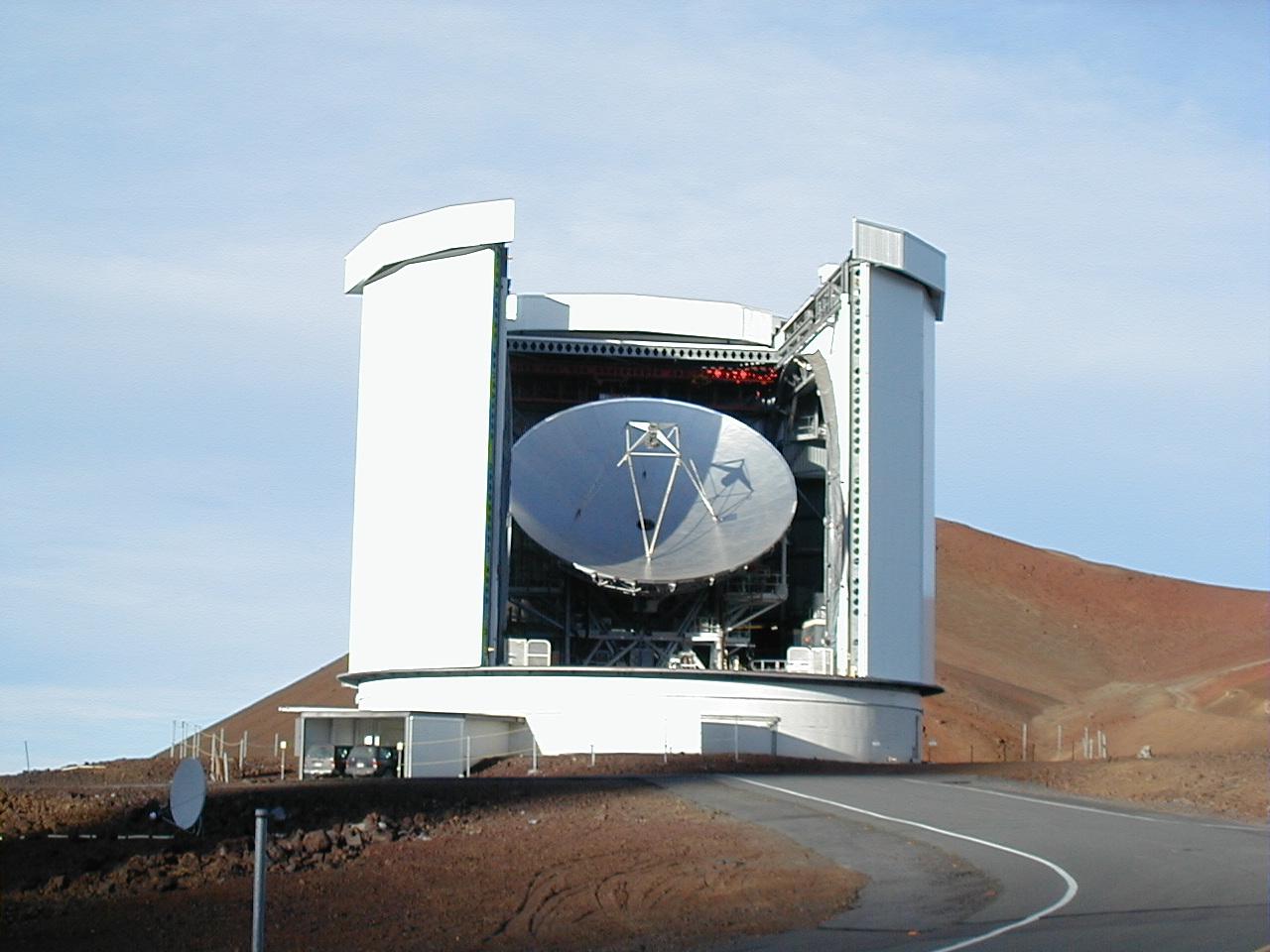
Image courtesy of
Royal Observatory of Edinburgh
The dish is made up of 276 panels, each of which can be moved and tilted independently. Note the very small size of the secondary mirror, which is only 0.75 meters in diameter.

Image courtesy of
East Asian Observatory
At an altitude of over 4000 meters above sea level, the atmosphere is just starting to become transparent again at wavelengths approaching one micron. The astronomers here look through two windows, around 450 and 850 microns. (Note that the wavelength axis in the figure below runs opposite to all the other figures showing transmission as a function of wavelength)
![]()
Atmospheric transmission on Mauna Kea courtesy of
JCMT and East Asian Observatory
One of the main instruments on the JCMT is a second-generation array detector called Submillimetre Common-Use Bolometer Array 2 (SCUBA-2). This instrument takes images at two wavelengths -- 450 and 850 microns -- simultaneously, in a field of view about 7 arcminutes wide. Each array contains about 5000 individual bolometers, split between four sub-arrays, with small gaps running between them.
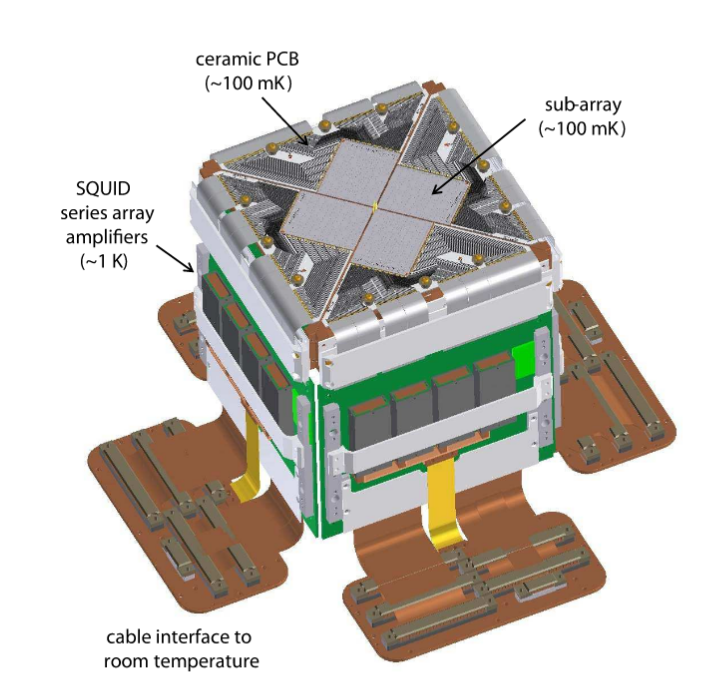
Figure 1 taken from
Holland et al., MNRAS 430, 2513 (2013)
The detectors here, a type called Transition Edge Sensors, operate at a temperature even lower than those on SPIRE. They work at 0.075 Kelvin! Even at these very low temperatures, not all the pixels in each sub-array are working perfectly, as these maps of the dark current show.
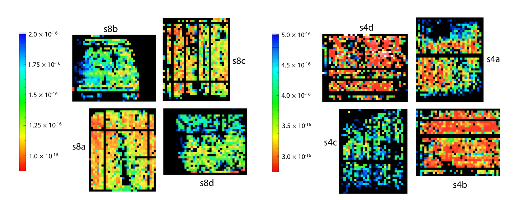
Taken from Figure 9 of
Holland et al., MNRAS 430, 2513 (2013)
In order to measure the light from a continuous region of the sky, without "holes" due to the bad pixels, the JCMT can be scanned in several different patterns over the region of interest, so that each little patch of sky is sampled many times by different pixels. The figure below shows the DAISY pattern on top, and the PONG pattern on the bottom.
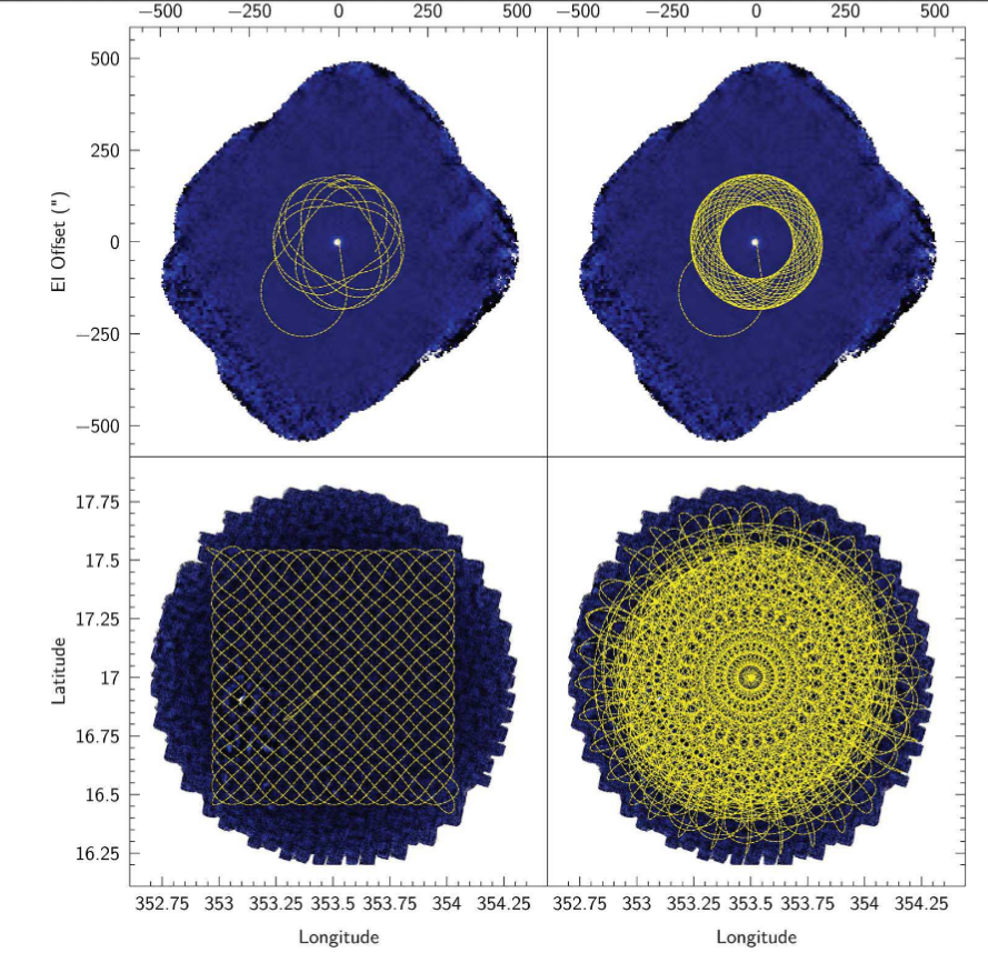
Taken from Figure 11 of
Holland et al., MNRAS 430, 2513 (2013)
The result of a repeated DAISY pattern is an image with lots of "exposure time" at the center of the field, but successively less at larger distances from the center.
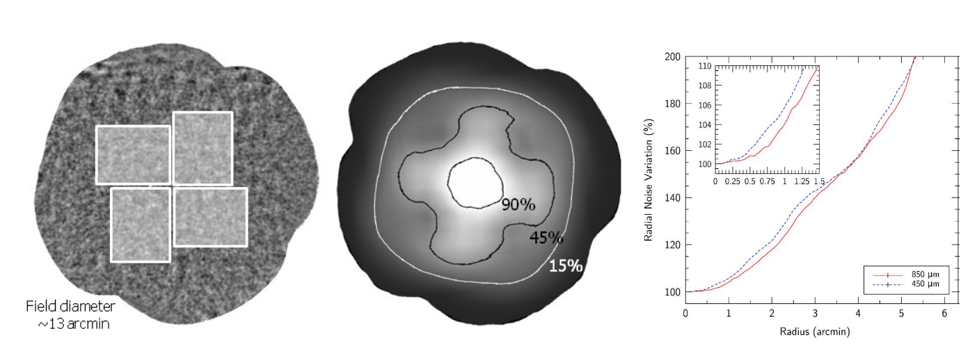
Taken from Figure 12 of
Holland et al., MNRAS 430, 2513 (2013)
Below is an example of what SCUBA-2 can see when looking at a bright, nearby galaxy. In the left panel, an optical image is shown in grey, while 850-micron emission is overlaid in red; the right panel shows 850-micron emission alone.
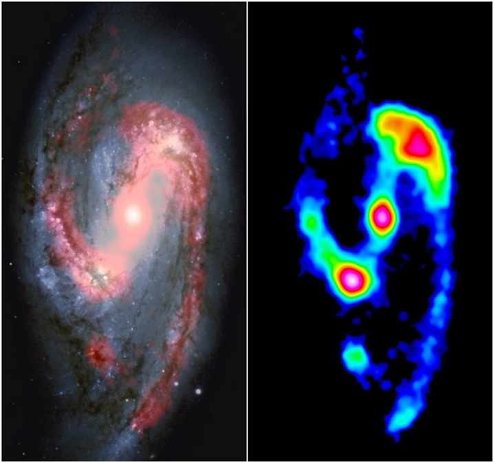
Image of M66 in the optical and 850 microns courtesy of
VLT/ESO, JAC, G. Bendo.
             Q:  What is the diffraction limit for this camera,
                    when working at 850 microns?  Express your
                    answer in arcseconds.
That may sound pretty lousy, but the combination of JCMT and SCUBA-2 can resolve some debris disks around nearby young stars.
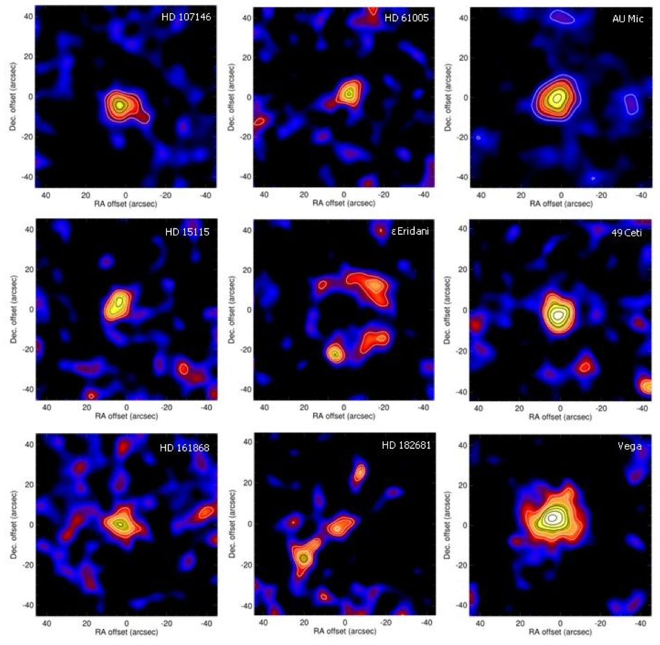
Images courtesy of
Holland, Matthews, Greaves and the SONS Team
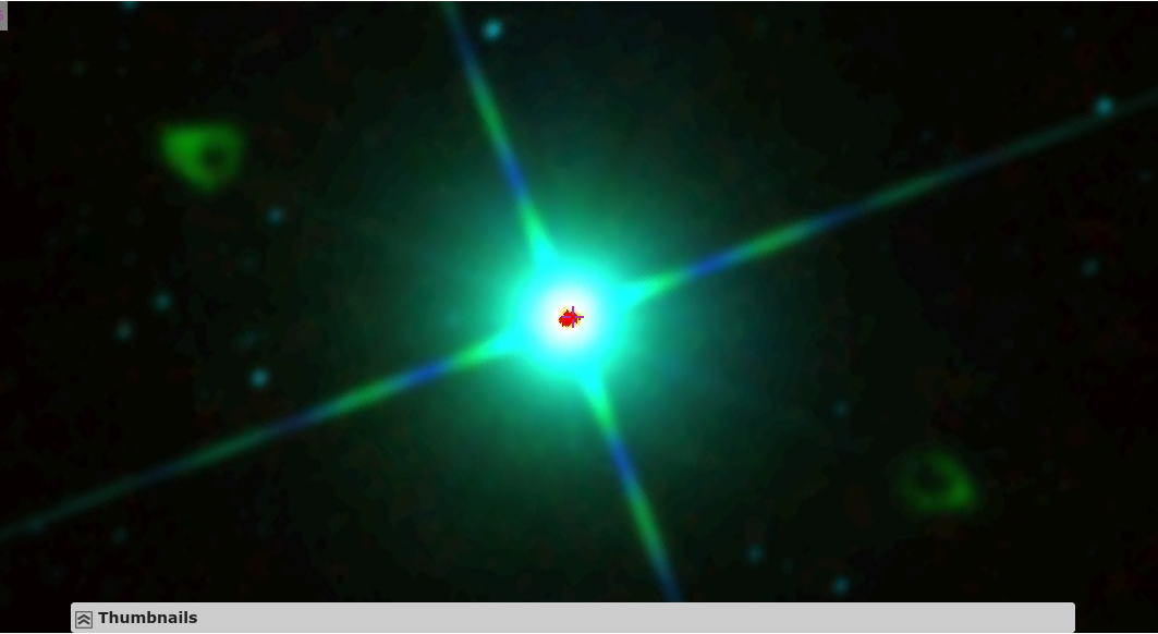
          Q:  Use the  Aladin Lite tool  to request an image
                  of Fomalhaut taken with the "DSS2 Red" survey,
                  the "allWISE" survey, and the "Akari/FIS" survey.
                  Set the field of view to 22 arcminutes.


    DSS Red (0.6 micron)   Allwise (3-22 micron)   Akari (65-140 micron)


          Q:  Compare those results to the image of Fomalhaut
                  taken by SCUBA-2 at 850 microns, shown below.

The short answer here is dust. Yup, just as in the mid-infrared, thermal emission by cool dust tends to show up all over the sky: from clouds within our own Milky Way Galaxy, to material in star-forming regions of other galaxies, to the dusty tori around many AGN.
Let's review the temperatures at which dust tends to emit most of its radiation.
     temperature           peak wavelength
        (K)                   (microns)
 ---------------------------------------------------

        3000

         300

          30

           3

 ---------------------------------------------------
It would seem that the best wavelengths to study dust clouds would be around 10 - 100 microns, since clouds with temperatures below 10 K aren't very common. In the SEDs shown below, emission from dust is dropping sharply as the wavelength increases beyond 100 microns.

Image 184 from
Infrared Astronomy
edited by L. Viktor Toth
Q: So why would someone want to look at longer wavelengths?
Well, this may sound familiar, but some people would like to see the light emitted by dust in high-redshift galaxies.
  Q:  A distant galaxy at redshift z=10 emits light with
         a rest wavelength of 100 microns.  What is the
         wavelength at which we observe that light?
If astronomers choose some bright, local, target, such as the debris disk around some nearby star in our own Milky Way Galaxy, then taking a picture of it with far-IR telescopes isn't so hard.
For example, the star HD 76582 is surrounded by a disk of dusty material which glows brightly in these mid-IR images taken by Herschel:
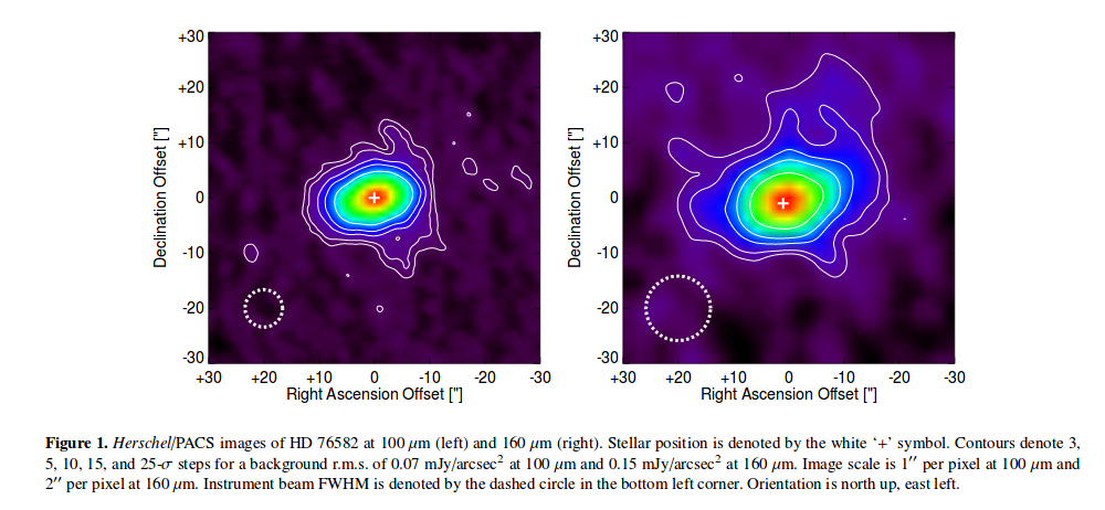
Figure 1 taken from
Marshall et al., MNRAS 459, 2893 (2016)
and the disk is easy to identify in these far-IR images taken with SCUBA-2 on JCMT. Note that the noise (or faint sources) in the background is rather higher at these longer wavelengths, though.

Figure 1 taken from
Marshall et al., MNRAS 459, 2893 (2016)
But when astronomers try to observe very distant galaxies in the far-IR -- which are very faint, of course, just barely (if at all) rising above the background -- they run into confusion: many regions of the sky contain so many sources, so close together, that it's not really clear which blob in this image corresponds to which blob in that image.
For example, compare these images of a region in the COSMOS/CANDELS field, centered on (J2000) RA = 10:30:00, Dec = +02:20:00, taken with SCUBA-2 on JCMT (450 microns, left) and with SPIRE on Herschel (500 microns, right).
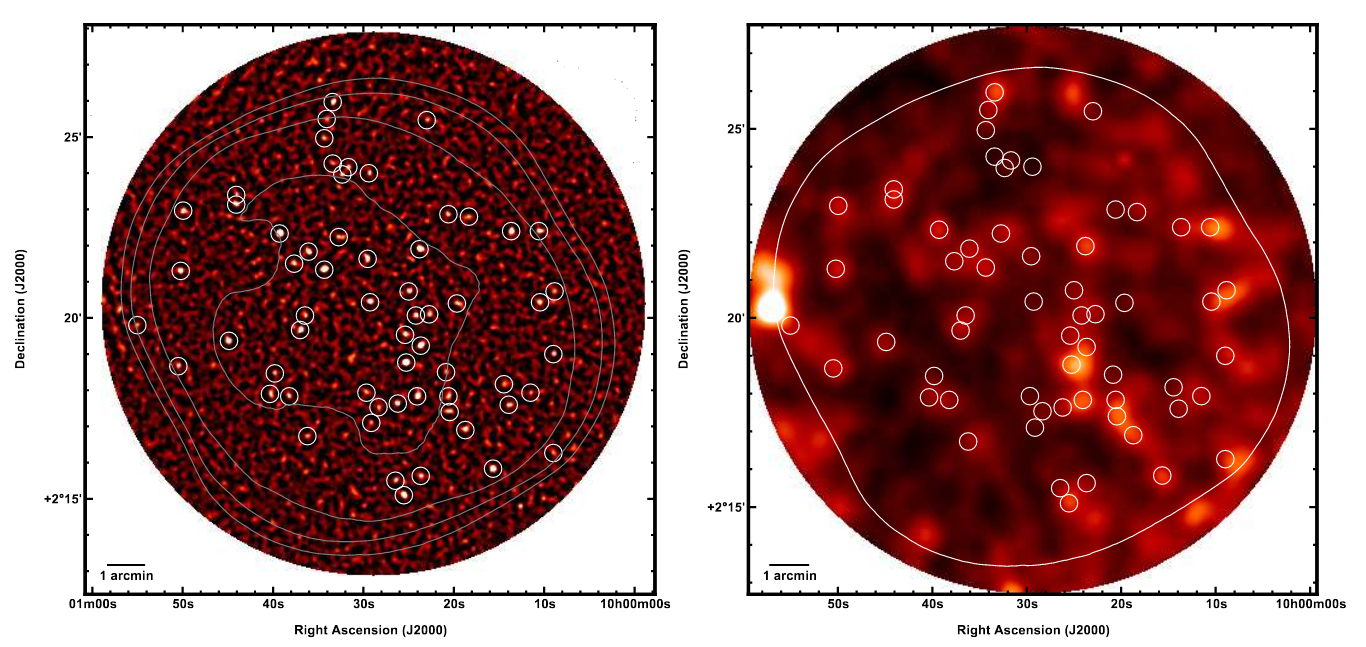
Figure 1 taken from
Geach et al., MNRAS 432, 53 (2013)
It's very frustrating when one compares the far-IR detections to optical or near-IR images. Which of the optical sources (if any) is responsible for the emission at far-IR wavelengths?
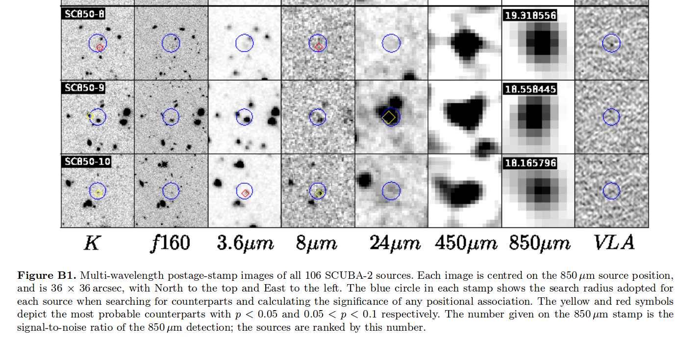
A small portion of Figure B1 from
Koprowski et al., MNRAS 458, 4321 (2016)
          Q:  Use the
                   CANDELS survey at MAST website
                  to look at the COSMOS field, epoch 01;
                  choose the F160_F125 combination view.

              Zoom in and out until you can roughly match the
                  field of view of the SCUBA-2 images.

              Can you find any sources in the HST image
                  which correspond to those in the far-IR images?
Why is this issue of confusion such a big deal in the far-IR? There are at least two reasons, one rather obvious and the other quite counterintuitive. While the second reason may not be very signficant in this particular context, let's discuss it a bit, since it may be more important in other high-redshift studies.
First, the really important reason: at the long wavelengths of the far-IR surveys, the diffraction limit causes each source to appear big and blurry.
  Q:  Compute the angular size of the Airy disk for each of the
          following instruments:

    telescope     diameter      wavelength         Airy disk size
                    (meters)     (microns)            (arcsec)
  -------------------------------------------------------------------

      HST           2.4            2

    Spitzer         0.85          24

     Herschel       3.5          450

      JCMT         15            850

  -------------------------------------------------------------------
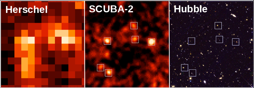
Image courtesy of SCUBA-2 News Blog
It is diffraction that causes the very distant far-IR galaxies to appear as big, blurry blobs, and thus to overlap each other. Rats.
But just how big SHOULD these early galaxies be? Suppose that a bright star-forming region in a young galaxy has a size of about L = 1 kpc. How large would this appear at a range of distances?
     true size        distance from Earth     apparent angular size
      L = 1 kpc              D (Mpc)               θ (arcsec)
-----------------------------------------------------------------------
         1 kpc               1 Mpc

         1                  10

         1                 100

         1               1,000

         1              10,000

-----------------------------------------------------------------------
You can work out the answers with simple trigonometry if you assume that the universe is Euclidean .... but is it really? Based on our best measurements, the answer is "no, not on large scales." If you really want to compute the properties of high-redshift galaxies properly, you will need to take into account the curvature of the universe. Fortunately, someone else has done the hard work for you:
     true size        redshift       comoving distance   angular size
      L = 1 kpc          z               D (Mpc)         θ (arcsec)
-----------------------------------------------------------------------
         1 kpc          0.001

         1              0.01

         1              0.1

         1              1

         1             10

-----------------------------------------------------------------------
Note that the apparent angular size of objects does not decrease in a simple linear manner; in fact, after a certain redshift, the angular size of objects starts to INCREASE, at least for universes with properties similar to our own.
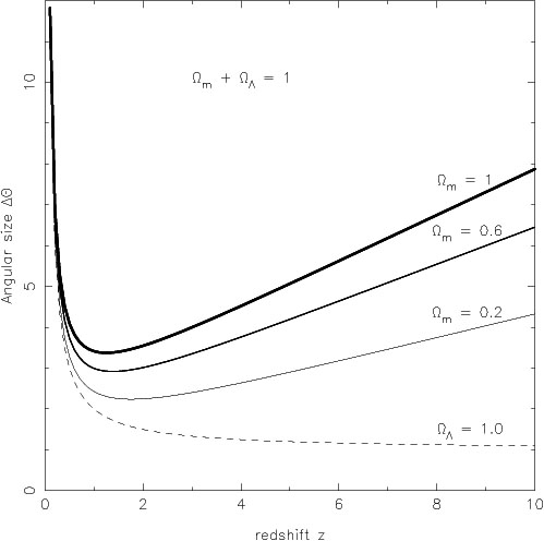
Figure 10 taken from
Sahni and Starobinsky, International Journal of Modern Physics D, Volume 9, Issue 04, pp. 373-443 (2000).
While this effect isn't very important for far-IR observations, it is something to keep in mind, if you happen to be interested in the earliest galaxies.
Copyright © Michael Richmond.
This work is licensed under a Creative Commons License.